44 Design and specifications are subject to change without notice 01/2008
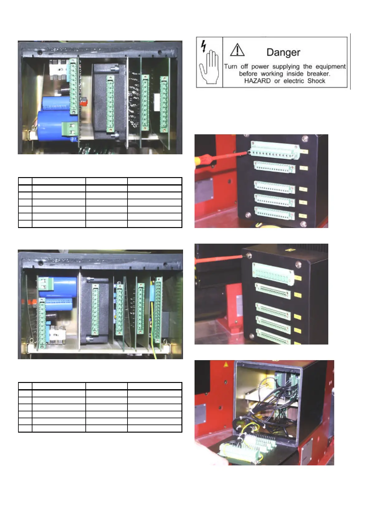
6.2.3 Layout of control PCB inside control box
Fig. 53 Control box inside (w/o SEL unit)
- - -
NEKO unit (ED trip) 128 750 R1 equipment to left
Voltage converter 128 730 R2-R4 equipment to left
SU-control unit 128 700 equipment to right
- - -
Table 5 Layout of control PCBs inside the box w/o SEL
Fig. 54 Control box inside (with SEL unit)
NEKO unit (ED trip) 128 750 R1 equipment to right
Voltage converter 128 730 R2-R4 equipment to right
SU-control unit 128 700 equipment to left
SU-control unit 128 700 equipment to right
- - -
Table 6 Layout of control PCBs inside the box with SEL
Attention:
• The isolation plates between the control boards and
at the wall of the box have to be always present!
• In older systems it may be the control boards are in-
stalled 180° turned!
6.2.4 Replacement of the control boards
• OPEN the breaker.
• Disconnect power supply, and pull out all the plugs
from control box’s terminals.
• In case of NEKO control unit inside, wait 1 minute
untill capacity will discharge.
Fig. 55-1 Unscrew and remove all the plugs
Fig. 55-2 Unscrew four bolts of the box cover
Fig. 55-3 Carefully move down the box cover
1 2 3 4 5 6
1 2 3 4 5 6
 Loading...


