– 47 –
The control display will flash on and off in the
display while the lock motor is in motion. When
the door is locked, the words LOCKED DOOR
remain lit in the display.
The cam on the motor performs two functions:
• Positions the lock hook in the door to prevent
opening during the CLEAN operation.
• Operates the lock switches which tell the
control if the door is unlocked or locked and
ready for CLEAN operation.
Note: When the door is either being locked or
unlocked, both lock switches will be in the open
position.
3
2
1
5
7
DOOR LATCH OUTPUT PIN 5, -25VDC
AT ALL TIMES MEASURED TO GROUND
DOOR UNLATCHED INPUT PIN
DOOR LATCHED INPUT PIN
SENSOR AND LOCK
SWITCH CONNECTORS
LOCK SW. #1
LOCK
SW. #2
LOCK SW. CIRCUIT
UNLOCKED
THERMAL SWITCH
3
2
1
5
7
DOOR LATCH OUTPUT PIN 5, -25VDC
AT ALL TIMES MEASURED TO GROUND
DOOR UNLATCHED INPUT PIN
DOOR LATCHED INPUT PIN
SENSOR AND LOCK
SWITCH CONNECTORS
LOCK SW. #2
LOCK
SW. #1
LOCK SW. CIRCUIT
LOCKED
THERMAL SWITCH
HTI
HTI Tech & I
n
d
HTSYG048B002FL45
-
0001
Date:
Made in China
LOCK SW.
N.O. CONTACT
CLOSED
UNLOCK SW.
N.O. CONTACT
OPEN
CAM IN
LOCK POSITION
LOCKED
HT
I
HTI Tech & Ind
HT
SY
G048B00
2FL
45
-0001
Date:
Made in
China
LOCK SW.
N.O. CONTACT
OPEN
UNLOCK SW.
N.O. CONTACT
CLOSED
CAM IN
UNLOCK POSITION
UNLOCKED
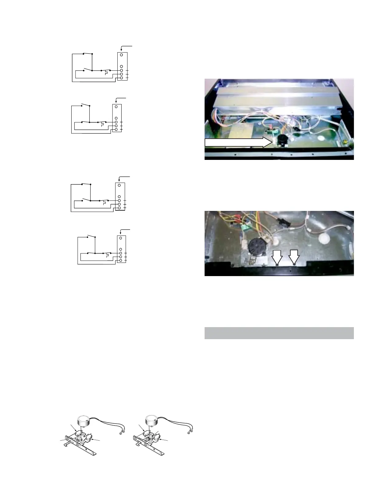
3. Remove the 2 hex-head screws that hold the
door latch assembly in place. Pull the
assembly out to access the wiring harness
connectors.
To remove the door latch assembly:
1. Remove the maintop burner assembly (see
Maintop Burner Assembly).
2. Remove the upper and lower heat shield (see
Upper and Lower Heat Shield).
Door Latch Assembly
4. Note the placement of the wiring, then
disconnect all wires to the door latch
assembly.
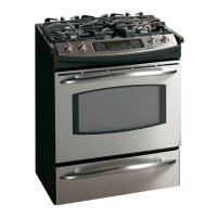
Motorized Door Lock Circuit Information
The lock motor circuits and the lock switch circuit
control the locking and unlocking of the door.
The lock motor circuit applies voltage (120 VAC)
to the lock motor. This circuit is from L, through
the door switch, lock relay, and lock motor to
neutral.
For this circuit to be complete, the lock relay must
be energized by the ERC and the door must be
closed. An open oven door results in LOCK
DOOR flashing in the display after the control has
been programmed for clean and START has
been depressed.
(Continued next page)
5
4
3
6
8
DOOR UNLATCHED INPUT PIN
DOOR LATCHED INPUT PIN
SENSOR AND LOCK
SWITCH CONNECTORS
LOCK SW. #1
LOCK
SW. #2
LOCK SW. CIRCUIT
UNLOCKED
THERMAL SWITCH
DOOR LATCH OUTPUT PIN 5, -25V DC
5
4
3
6
8
DOOR LATCH OUTPUT PIN 5, -25V DC
DOOR UNLATCHED INPUT PIN
DOOR LATCHED INPUT PIN
SENSOR AND LOCK
SWITCH CONNECTORS
LOCK SW. #2
LOCK
SW. #1
LOCK SW. CIRCUIT
LOCKED
THERMAL SWITCH
JGS968 & J2S968
JGSP48
 Loading...