EasyManuals Logo
Home>GE>Monitor>QuickPanel+ IC755CxS10CDx

GE QuickPanel+ IC755CxS10CDx User Manual

GE QuickPanel+ IC755CxS10CDx
118 pages
To Next Page IconTo Next Page
To Previous Page IconTo Previous Page
Page #68 background imageLoading...
Page #68 background image
68 GFK-2847W
For public disclosure
QuickPanel Operator Interface User
Manual
75
mm
m
m
5
7
75
mm
(2.95
in)
100 mm
(3.94 in)
5.5 VESA Arm Mounting
The QuickPanel
+
unit can be installed on a commercially available Video Electronics Standards Association (VESA) MIS-D
arm, stand, or apparatus that complies with the UL1678 standard.
Note Refer to the mounting arm manual for instructions.
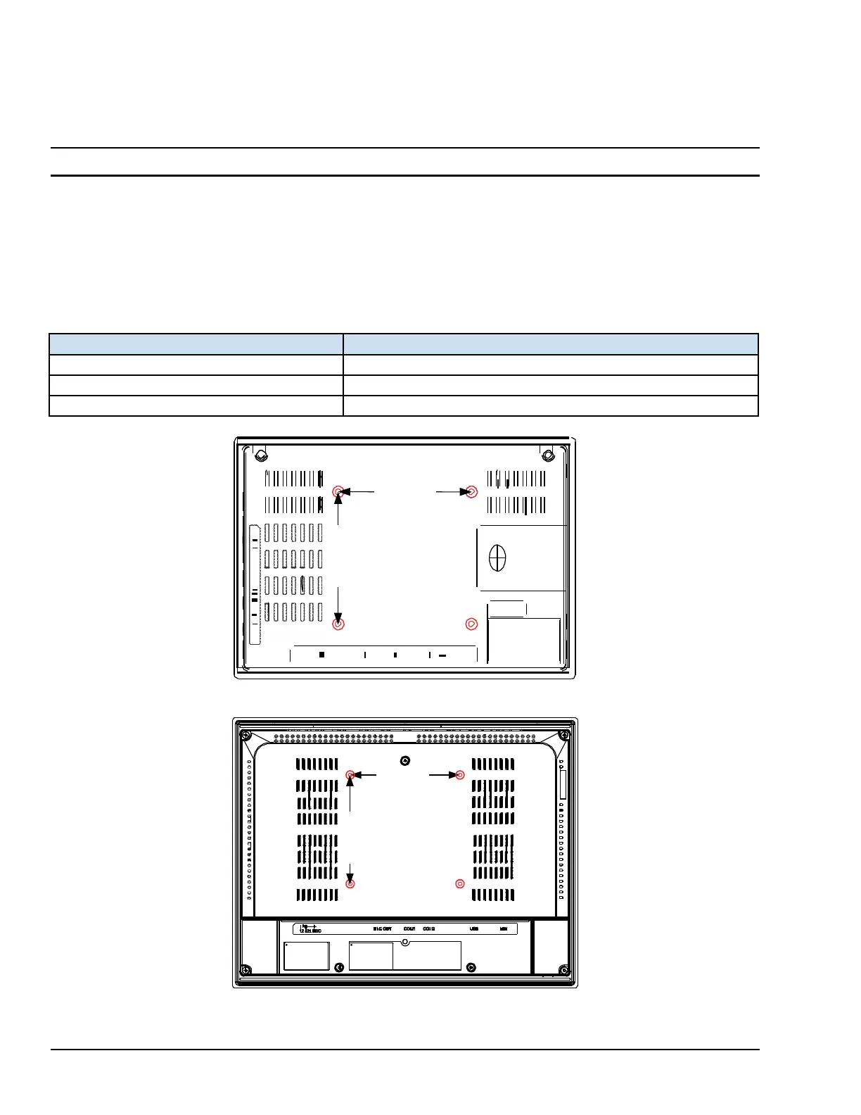
To VESA mount the QuickPanel
+
unit: use the mounting holes located on the back of the unit (displayed in the
following figures).
The mounting holes for IC755CxS06RDx and IC755CxW07CDx attach with M4 screws that are 6 mm (0.24 in) or less in
length.
The mounting holes for IC755CxSxxCDx attach with M4 screws that are 8 mm (0.32 in) or less in length.
Torque Range for Mounting M4
Screws
Display Unit
Torque Range
IC755CxS06RDx
0.7 to 0.8 Nm (6.2 to 7.1 in-lb)
IC755CxW07CDx
0.7 to 0.8 Nm (6.2 to 7.1 in-lb)
IC755CxSxxCDx
1.0 to 1.2 Nm (8.9 to 10.6 in-lb)
75
mm
(2.95
in)
IC755CxW07CDx or IC755CxS06RDx VESA Mounting Holes
100 mm
(3.94 in)
IC755CxSxxCDx VESA Mounting
Holes

Table of Contents

Questions and Answers:

Question and Answer IconNeed help?

Do you have a question about the GE QuickPanel+ IC755CxS10CDx and is the answer not in the manual?

GE QuickPanel+ IC755CxS10CDx Specifications

General IconGeneral
BrandGE
ModelQuickPanel+ IC755CxS10CDx
CategoryMonitor
LanguageEnglish

Related product manuals