3.3.2 Power Cables
Supply power cable must be connected to TM1 terminal block, terminals L1(L) and L3(N) for
single phase 200V supply, L1(L), L2, L3(N) for three phase 200V supply and L1, L2, L3 for
three phase 400V supply.
Motor cable must be connected to TM1 terminals. T1, T2, T3.
Warning: Connection of Supply line cable to terminals T1,T2& T3 will result in serious
damage to the drive components.
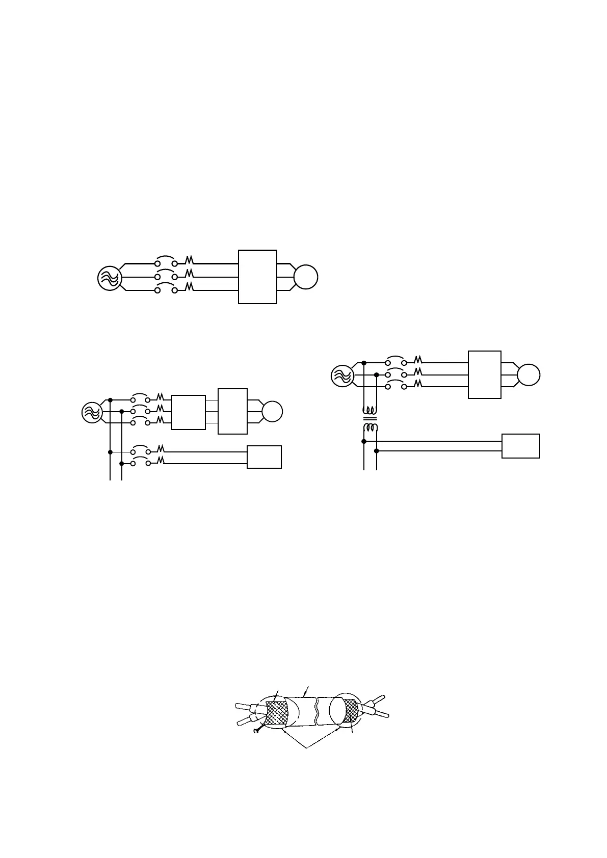
Example power connections: Inverter with dedicated power line.
Install a Supply RFI filter or Isolation transformer when the power source is
shared with other high power electrical equipment as shown below.
Inverter IM
Machine
Insulation transformer
Power
MCCB
3.3.3 Control Cable selection and Wiring
Control cables should be connected to terminal block TM2.
Choose power & Control cables according to the following criteria:
Use copper wires with correct diameter and temperature rating of 60/75°C.
Minimum cable voltage rating for 200V type inverters should be 300VAC.
Route all cables away from other high voltage or high current power lines
to reduce interference effects.
Use a twisted pair shielded cable and connect the shield (screen) wire to the ground
terminal at the inverter end only. Cable length should not exceed 50 meters.
Shielding sheath
Inverter IM
Machine
RFI
Filter
Power
MCCB
Connect the shield to inverter
ground terminal
 Loading...


