EasyManuals Logo
Home>gefran>Inverter>BDI50 Series

gefran BDI50 Series User Manual

gefran BDI50 Series
184 pages
To Next Page IconTo Next Page
To Previous Page IconTo Previous Page
Page #39 background imageLoading...
Page #39 background image
3-29
3.6 Terminal Description
3.6.1 Description of main circuit terminals
Terminal symbols
TM1 Function Description
L1(L)
Main power input, single phase
L1(L) / L3(N)
three phase(200V)L1(L) / L2 / L3(N)
three phase (400V)
L1 / L2 / L3
L2
L3(N)
P*
externally connected braking resistor
BR*
T1
Inverter output, connect to U, V, W terminals of motor
T2
T3
Ground terminal
*P, BR for BDI50-…-KBX-2T / BDI50-…-KBX-4
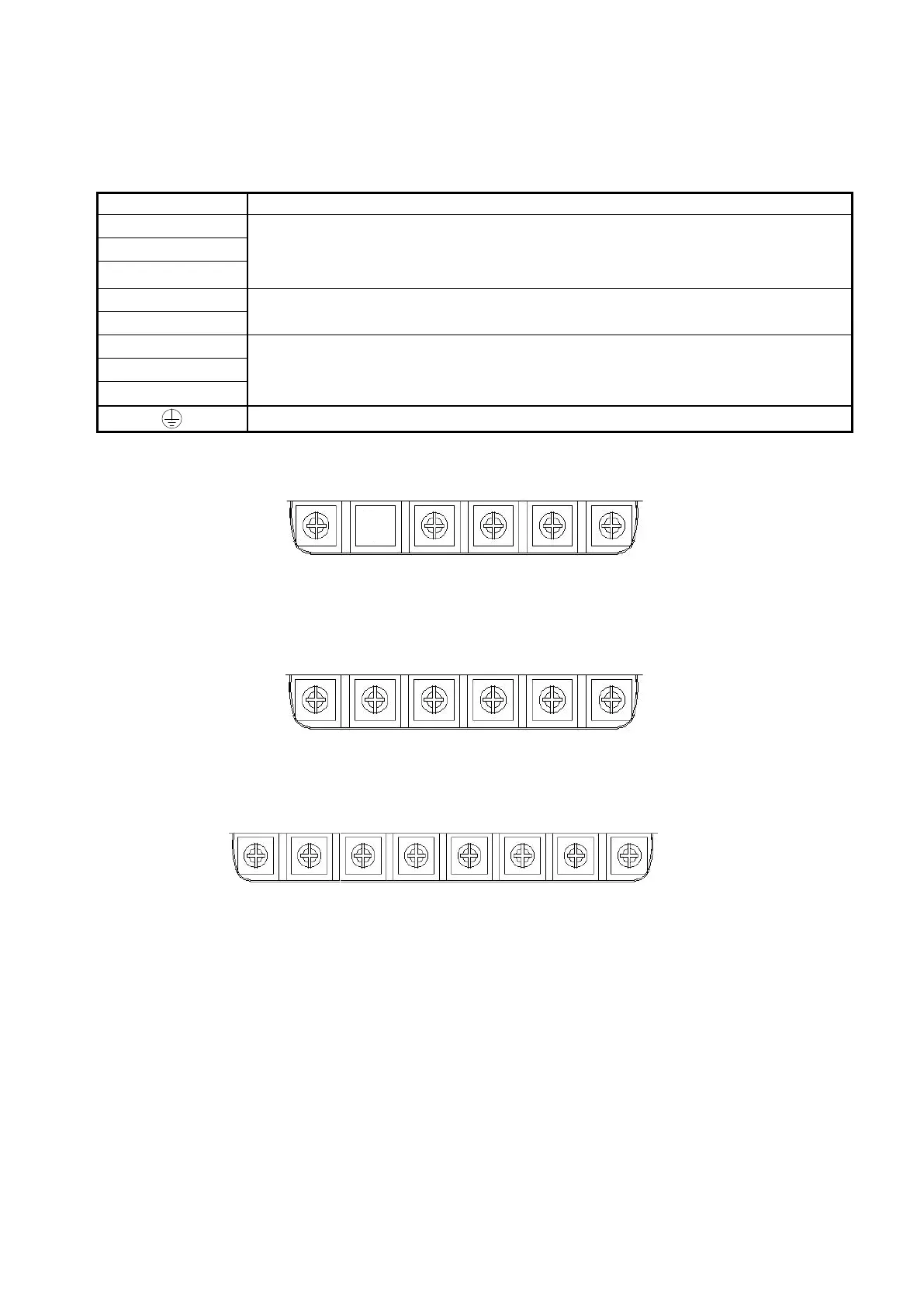
Single phase
Note: the screw on L2 terminal is removed for the single phase input supply models.
Three phase (BDI50-…-KXX-2T, 200V series)
Three phase (BDI50-…-KBX-2T & BDI50-…-KBX-4 series)
L1(L) L2 L3(N) T1 T2 T3
L1 L2 L3 P BR T1 T2 T3

Table of Contents

Questions and Answers:

Question and Answer IconNeed help?

Do you have a question about the gefran BDI50 Series and is the answer not in the manual?

gefran BDI50 Series Specifications

General IconGeneral
Brandgefran
ModelBDI50 Series
CategoryInverter
LanguageEnglish

Related product manuals