EasyManuals Logo
Home>gefran>Inverter>BDI50 Series

gefran BDI50 Series User Manual

gefran BDI50 Series
184 pages
To Next Page IconTo Next Page
To Previous Page IconTo Previous Page
Page #151 background imageLoading...
Page #151 background image
App 3-1
Appendix 3 BDI50 Communication protocol
A3.1 Modbus communication protocol
1. Communication Data Frame
BDI50 series inverter can be controlled by a PC or other controller with the Communication
protocol, Modbus ASCII Mode & Mode RTU, RS485 or RS232. Frame length maximum 80
bytes.
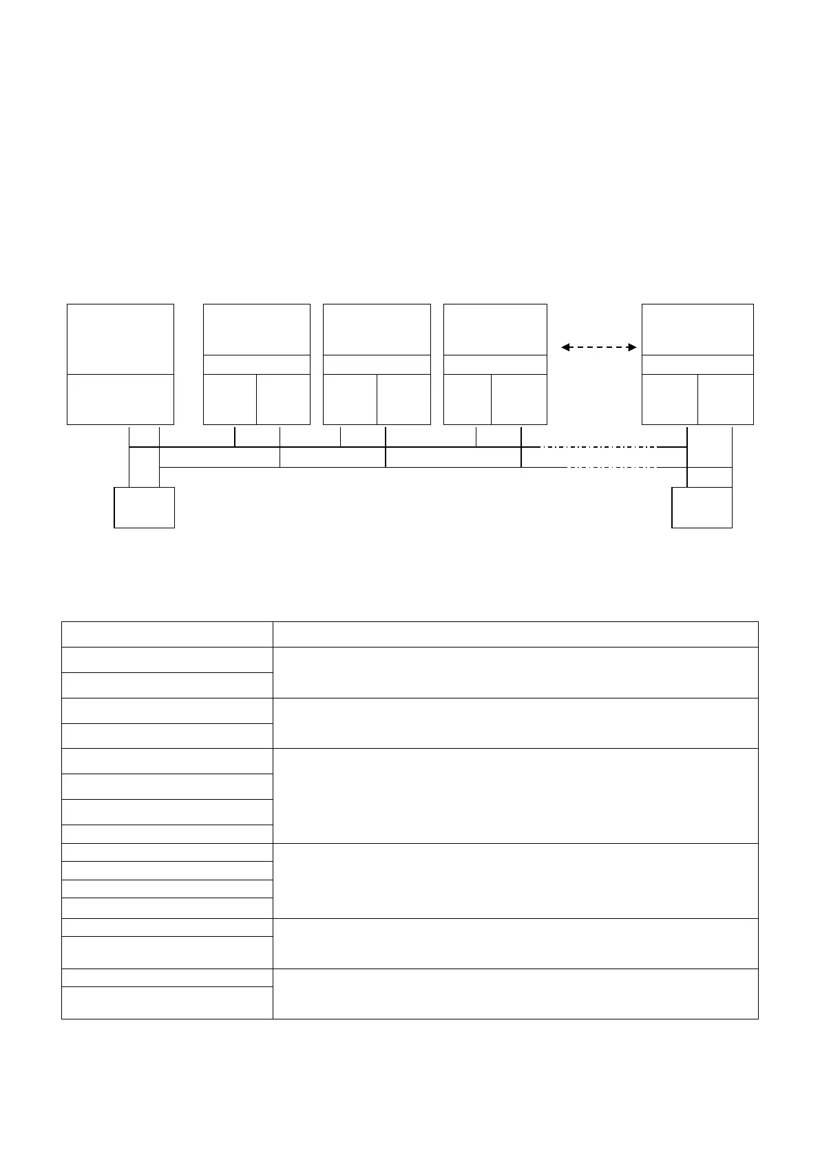
1.1 Hardware installation
controller
(PLC / HMI
or
PC)
Slave BDI50
Station 01
Slave BDI50
Station 02
Slave BDI50
Station 03
Slave BDI50
Station FE
Option Card
Option Card
Option Card
Option Card
RS-485
Interface
A B A B A B A B
Response
Request
** The network is terminated at each end with an external terminating resistor (120Ω1/4w)**
1.2 Data format ASCII MODE
STX(3AH)
Start bit = 3AH
Address Hi
Communication Address(Station):
2-digit ASCII Code
Address Lo
Function Hi
Function Code (command):
2-digit ASCII Code
Function Lo
Command Start Address
Command Start byte:
4-digit ASCII Code
Command Start Address
Data length
The length of the command:
4-digit ASCII Code
Data length
Data length
Data length
LRC Check Hi
LRC Check Code:
2-digit ASCII Code
LRC Check Lo
END Hi
End Byte :
END Hi = CR(0DH), END Lo= LF(0AH)
END Lo
120Ω
1/4w
120Ω
1/4w

Table of Contents

Questions and Answers:

Question and Answer IconNeed help?

Do you have a question about the gefran BDI50 Series and is the answer not in the manual?

gefran BDI50 Series Specifications

General IconGeneral
Brandgefran
ModelBDI50 Series
CategoryInverter
LanguageEnglish

Related product manuals