Appendix-2 Instructions for UL
App 2-4
■ Drive Short-Circuit Rating
This drive has undergone the UL short-circuit test, which certifies that during a short circuit in the power supply the current flow will
not rise above value. Please see electrical ratings for maximum voltage and table below for current.
• The MCCB and breaker protection and fuse ratings (refer to the preceding table) shall be equal to or greater than the short-circuit
tolerance of the power supply being used.
• Suitable for use on a circuit capable of delivering not more than ( A ) RMS symmetrical amperes for ( Hp ) in 240 / 480 V class
drives motor overload protection.
◆ Drive Motor Overload Protection
Set parameter 02-01 (motor rated current) to the appropriate value to enable motor overload protection. The internal motor overload
protection is UL listed and in accordance with the NEC and CEC.
■ 02-01 Motor Rated Current
Setting Range: Model Dependent
Factory Default: Model Dependent
Set 02-01 to the full load amps (FLA) stamped on the nameplate of the motor.
■ 08-05 Motor Overload Protection Selection
The drive has an electronic overload protection function (OL1) based on time, output current, and output frequency, which protects the
motor from overheating. The electronic thermal overload function is UL-recognized, so it does not require an external thermal overload
relay for single motor operation.
This parameter selects the motor overload curve used according to the type of motor applied.
Overload Protection Settings
Sets the motor overload protection function in 08-05 according to the applicable motor.
Setting 08-05 = XXXX0. Disables the motor overload protection function when two or more motors are connected to a single inverter.
Use an alternative method to provide separate overload protection for each motor such as connecting a thermal overload relay to the
power line of each motor.
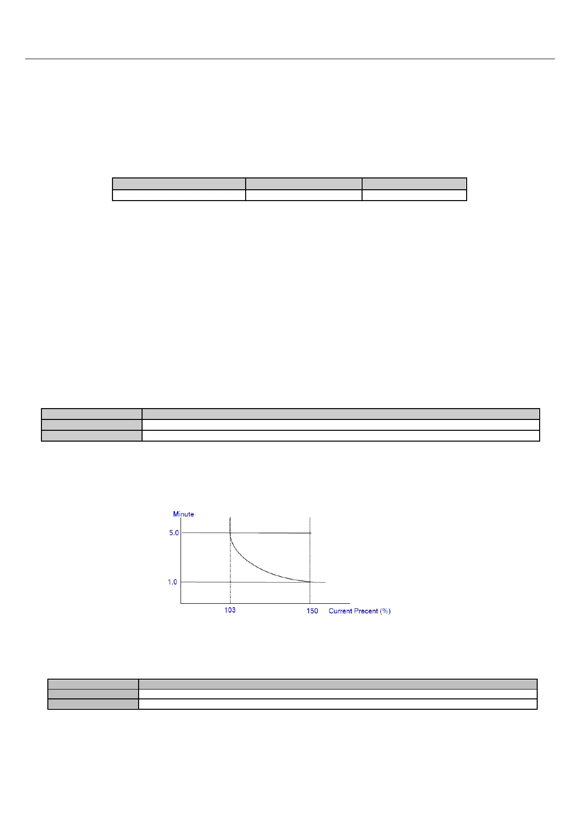
Motor Overload Protection Time
■ 08-06 Motor Overload Operation Selection
Free Run to Stop (default setting)
 Loading...


