EasyManuals Logo
Home>gefran>Inverter>BDI50 Series

gefran BDI50 Series User Manual

gefran BDI50 Series
184 pages
To Next Page IconTo Next Page
To Previous Page IconTo Previous Page
Page #40 background imageLoading...
Page #40 background image
3-30
3.6.2 Description of control circuit terminal
Size 1 & Size 2
Terminal symbols
TM2 Function Description
Signal Level
RA
Relay output terminal 250VAC/1A (30VDC/1A)
RB
COM
S1~S5 (COMMON)
NPN
±15%,Max output current 30mA
24V
S1~S5 (COMMON)
PNP
S1~S5
Multi-function input terminals
(refer to group 3)
24 VDC, 4.5 mA, Optical coupling
isolation
(Max,voltage 30 Vdc,
Input impedance 6kΩ)
10V
Built in Power for an external speed
potentiometer
10V (Max current:20mA)
AVI
Analog voltage input
Specification : 0 / 2~10 VDC
(choose by parameter 04-00)
0~10V (Input impedance 200kΩ)
ACI
Analog current input
Specification : 0 / 4~20mA
(choose by parameter 04-00)
0~20mA (Input impedance 499
Ω)
AO
Multi function analog output terminal.
Maximum output 10VDC/1mA
0~10V (Max current 2mA)
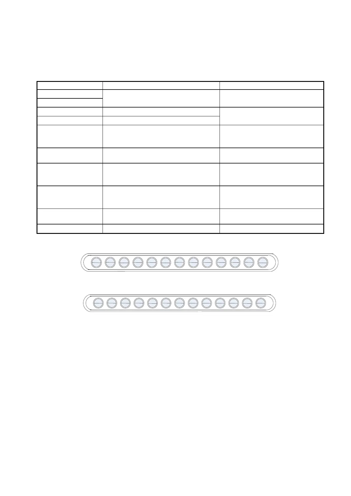
AGND
Analog ground terminal
NPN:
RA RB COM S1 S2
S3
S4 S5 10V AVI ACI AO AGND
PNP:
RA RB +24V S1 S2 S3 S4 S5 10V AVI ACI AO AGND

Table of Contents

Questions and Answers:

Question and Answer IconNeed help?

Do you have a question about the gefran BDI50 Series and is the answer not in the manual?

gefran BDI50 Series Specifications

General IconGeneral
Brandgefran
ModelBDI50 Series
CategoryInverter
LanguageEnglish

Related product manuals