Size 3 & Size 4
Relay output terminal, Specification: 250VAC/5A(30VDC/5A)
RA: Normally open RB: Normally close RC: common point
TM2 Function Description Signal Level
Common point of PNP input
±15%,Max output current 30mA SC
NPN/PNP selectable terminal.
NPN input: +24V&SC need to be shorted.
PNP input: COM&SC need to be shorted.
voltage reference point for S1~S5
S1~S5
Multi-function input terminals
(refer to group3)
24 VDC, 4.5 mA, Optical coupling
isolation
Input impedance 6kΩ)
10V
Built in Power for an external speed
potentiometer (Max output : 20mA)
10V,(Max current:20mA)
AVI/PTC
Analog voltage input/motor over
temperature protection signal input.
Specification: 0 / 2~10 VDC
(choose by parameter 04-00)
0~10V(Input impedance 200kΩ)
ACI
Specification: 0 / 4~20mA (choose by
0~20mA(Input impedance 499Ω)
AO
Multi function analog output terminal.
Maximum output 10VDC/1mA
0~10V(Max current 2mA)
NPN/PNP:
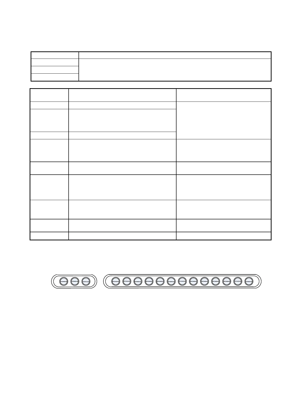
+24V SC COM S1 S2 S3 S4 S5 10V ACI AO AGND
RA RB RC
TM1 TM2
AVI
PTC
 Loading...


