The revolving magnetic field is driven by the engine
at constant speed. This constant speed is maintained
by a mechanical engine governor. Units with a 2-pole
rotor require an operation speed of 3600 rpm to deliv-
er a 60 Hertz AC output.
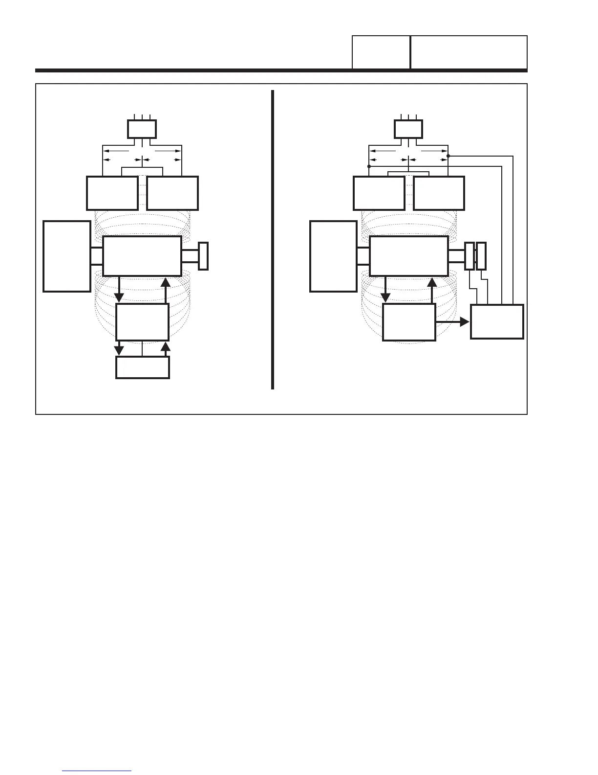
Generator operation may be described briefly as follows.
1. Some “residual” magnetism is normally present in the
Rotor, which is sufficient to induce approximately 1 to 2
Volts AC in to the Stator’s AC Power Windings and DPE
winding.
2. See Figure 8.
A. During startup, the “residual” voltage that
is induced into the DPE winding will initially
charge the capacitor to a greater potential.
When the capacitor is discharged the voltage
is in turn induced back into the Rotor which will
exponen tially raise the voltage to 120/240.
B. During startup, the “residual” voltage that is
induced into the DPE winding will turn on the
voltage regulator allowing DC excitation current
to be delivered to the rotor and raise the voltage
to 120/240.
PART 1
Page 12
GENERAL INFORMATION
SECTION 1.1
GENERATOR FUNDAMENTALS
CAPACITOR
STATOR
EXCITATION
WINDING
STATOR
POWER
WINDING
STATOR
POWER
WINDING
MAGNETIC
FIELD
MAGNETIC
FIELD
MLB = MAIN LINE
CIRCUIT BREAKER
ROTOR
TO LOAD
MLB
ENGINE -
DIRECT
DRIVE
AUTOMATIC
VOLTAGE
REGULATOR
+-
STATOR
EXCITATION
WINDING
STATOR
POWER
WINDING
STATOR
POWER
WINDING
MAGNETIC
FIELD
MAGNETIC
FIELD
SENSING
MLB = MAIN LINE
CIRCUIT BREAKER
ROTOR
TO LOAD
MLB
ENGINE -
DIRECT
DRIVE
120 VAC 120 VAC
240 VAC
120 VAC 120 VAC
240 VAC
A B
CAPACITIVE DISCHARGE DIRECT EXCITATION
Figure 8. Generator Operating Diagram

 Loading...


