Page 44
PROCEDURE:
The battery should have been checked prior to this
test and should be fully charged.
Set a voltmeter to measure DC voltage (12 VDC).
Connect the meter positive (+) test lead to the Starter
Contactor stud which has the small jumper wire con-
nected to the Starter. Connect the common (-) test
lead to the Starter Motor frame.
Set the Start-Stop Switch to its START position and
observe the meter. Meter should Indicate battery voltage,
Starter Motor should operate and engine should crank.
RESULTS:
1. If battery voltage is indicated on the meter but Starter
Motor did not operate, remove and bench test the
Starter Motor (see following test).
2. If battery voltage was indicated and the Starter Motor
tried to engage (pinion engaged), but engine did not
crank, check for mechanical binding of the engine or
rotor.
NOTE: If a starting problem is encountered, the
engine itself should be thoroughly checked to
eliminate it as the cause of starting difficulty. It is
a good practice to check the engine for freedom
of rotation by removing the spark plugs and turn-
ing the crankshaft over slowly by hand, to be sure
it rotates freely.
*
WARNING!: DO NOT ROTATE ENGINE WITH
ELECTRIC STARTER WITH SPARK PLUGS
REMOVED. ARCING AT THE SPARK PLUG
ENDS MAY IGNITE THE GASOLINE VAPOR
EXITING THE SPARK PLUG HOLE.
Figure 4. Starter Motor (SM)
CHECKING THE PINION:
When the Starter Motor is activated, the pinion gear
should move and engage the flywheel ring gear. If the
pinion does not move normally, inspect the pinion for
binding or sticking.
Figure 5. Check Pinion Gear Operation
TOOLS FOR STARTER PERFORMANCE TEST:
The following equipment may be used to complete a
performance test of the Starter Motor:
• Aclamp-onammeter.
• Atachometercapableofreadingupto10,000rpm.
•Afullycharged12voltbattery.
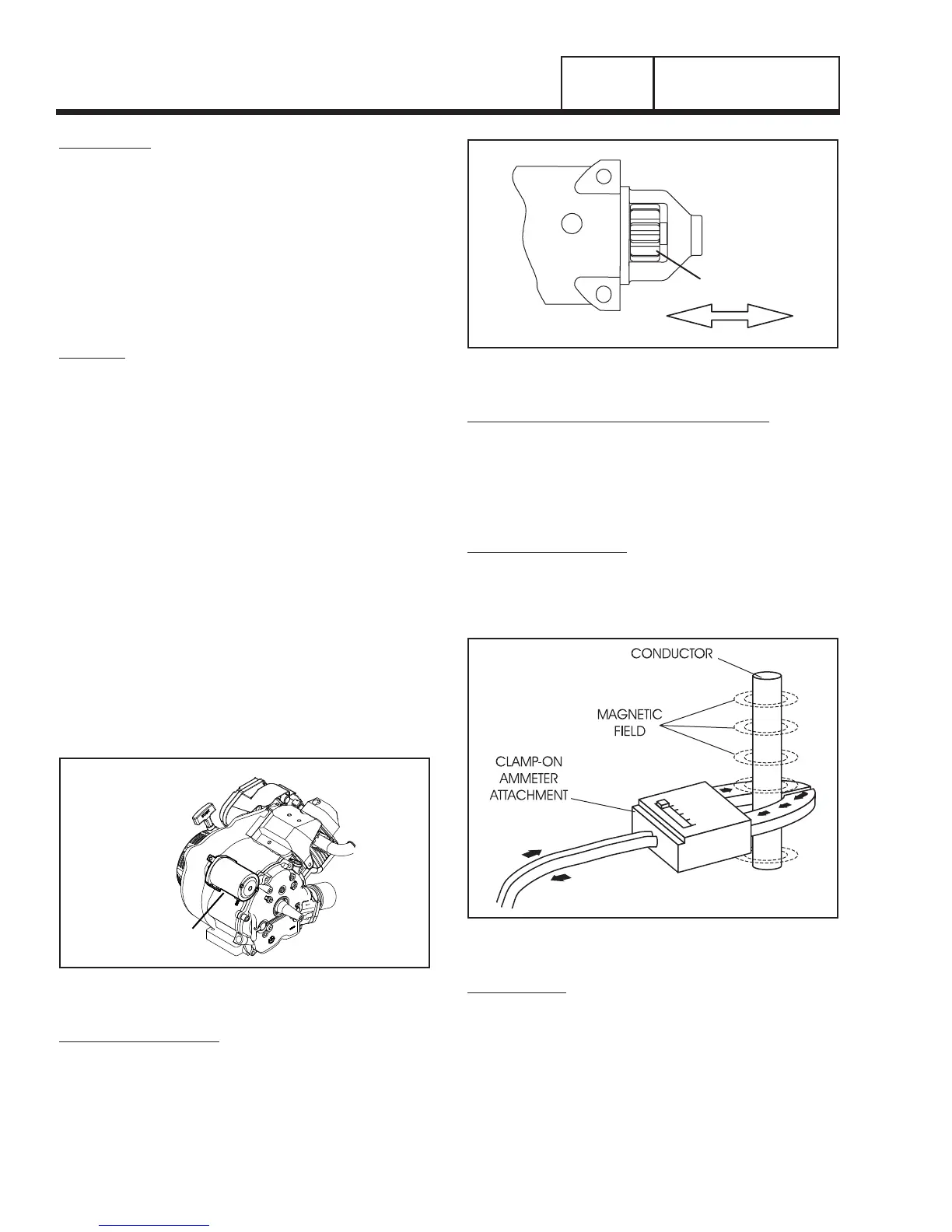
MEASURING CURRENT:
To read the current flow, in AMPERES, a clamp-on
ammeter may be used. This type of meter indicates
current flow through a conductor by measuring the
strength of the magnetic field around that conductor.
Figure 6. Clamp-On Ammeter
TACHOMETER:
A tachometer is available from your Generac Power
Systems source of supply. Order as P/N 042223. The
tachometer measures from 800 to 50,000 RPM (see
Figure 7).
PART 3
DC CONTROL
SECTION 3.3
DIAGNOSTIC TESTS

 Loading...


