INTRODUCTION
The “Diagnostic Tests” in this chapter may be per-
formed in conjunction with the “Flow Charts” of
Section 2.1 and Section 2.2. Test numbers in this
chapter correspond to the numbered tests in the
“Flow Charts”. It may be helpful to read Section 1.2,
“Measuring Electricity.”
NOTE: Test procedures in this Manual are not nec-
essarily the only acceptable methods for diagnos-
ing the condition of components and circuits. All
possible methods that might be used for system
diagnosis have not been evaluated. If any diag-
nostic method is used other than the method pre-
sented in this Manual, the technician must ensure
that neither his personal safety nor the product's
safety will be endangered by the procedure or
method that has been selected.
For visual pictures of the different configurations
of the stators and the wire numbers associated
with different components please see Figures 4
and 5 in Section 1.3, and Figure 3 in Section 1.4.
TEST 1 – CHECK NO-LOAD VOLTAGE AND
FREQUENCY
PROCEDURE:
1. Disconnect or turn OFF all electrical loads connected to
the generator.
2. Set a VOM to measure AC voltage.
3. Reset all circuit breakers to the on position.
4. Start the engine and let it stabilize and warm up.
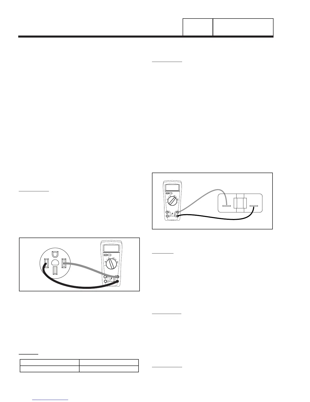
Figure 1. VOM Test Leads Connected to a 240 VAC
receptacle
6. Place the meter test leads into an outlet. See Figure 1.
7. Read the AC voltage.
8. Connect a AC frequency meter as described in Step 6.
9. Read the AC frequency.
RESULTS:
No Load Voltage
No Load Frequency
223.2 – 256.8 VAC 62.5 – 62.0 HZ
Refer back to Flow Chart.
TEST 2 – CHECK CIRCUIT BREAKER
PROCEDURE:
The generator has circuit breakers located on the
control panel. If outlets are not receiving power, make
sure the breakers are set to ON or “Closed”.
If a breaker is suspected to have failed, it can be
tested as follows:
1. Set a VOM to measure resistance.
2. With the generator shut down, disconnect all wires from the
suspected circuit breaker terminals to prevent interaction.
3. With the generator shut down, connect one meter test
lead to a one terminal of the breaker and the other
meter test lead to the other terminal. See Figure 2.
4. Set the breaker to its ON or “Closed” position. The meter
should read CONTINUITY.
5. Set the breaker to its OFF or “Open” position and the
meter should indicate INFINITY.
Figure 2. 20/30 Amp Breaker Test Points
RESULTS:
1. If the circuit breaker tests good, refer back to the flow
chart.
2. If the breaker tests bad, it should be replaced.
TEST 3 – CHECK CONTINUITY OF
RECEPTACLE PANEL
DISCUSSION:
Continuity of the receptacle panel is important
because it reflects that the receptacle has continuity
through the wiring and is physically connected to the
stator. Most stator winding values are between 0.01
and 0.02 Ohms of resistance. If a higher than normal
ohm reading is shown then a poor connection could
be the problem preventing that receptacle from receiv-
ing power.
PROCEDURE:
1. Set a VOM to measure Resistance.
Page 26
PART 2
AC GENERATORS
SECTION 2.3
AC DIAGNOSTIC TESTS

 Loading...


