INTRODUCTION
A typical brushed type portable generator will need 4
major components to function: a prime mover, a sta-
tor, a rotor, and a voltage regulator.
As the engine starts to crank, residual magnetism
from the rotor creates magnetic lines of flux. The lines
begin to cut the excitation winding and induce a small
voltage into the voltage regulator. The excitation volt-
age will power the voltage regulator and the voltage
regulator will start to sense AC voltage from Wires
S15 and S16. The lower voltage from the sensing
wires will cause DC excitation to the rotor to be driven
up until AC output is at desired level of 240VAC. Once
the generator has reached 240VAC it will maintain the
DC voltage, regulating the alternator when loads are
applied and removed.
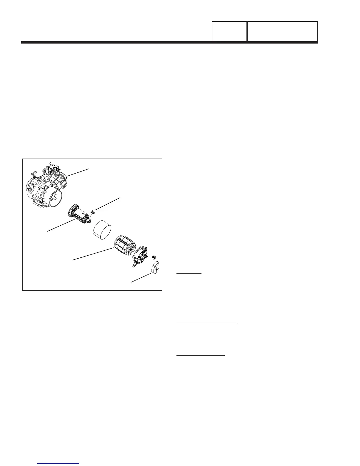
STATOR
ROTOR
ENGINE
BRUSHES
VOLTAGE REGULATOR
Figure 1. AC Generator Exploded View
STATOR ASSEMBLY
The stator has three windings wound separately
inside the can. Two are the power windings and are
located on Wire 44 (Hot) and Wire 33 (Neutral); the
other winding is located on Wire 11 (Hot) and Wire 22
(neutral). The third winding is called DPE winding or
Displaced Phase Excitation winding and is located on
Wire 2 and Wire 6.
BRUSH HOLDER AND BRUSHES
The brush holder is retained to the rear bearing car-
rier by means of two Taptite screws. A positive (+) and
a negative (-) brush are retained in the brush holder.
Wire 4 connects to the positive (+) brush and Wire
0 to the negative (-) brush. Rectified and regulated
excitation current are delivered to the rotor windings
via Wire 4, and the positive (+) brush and slip ring.
The excitation current passes through the windings
to the negative (-) slip ring and brush on Wire 0. This
current flow creates a magnetic field around the rotor
having a flux concentration that is proportional to the
amount of current flow.
ROTOR RESIDUAL MAGNETISM
The generator revolving field (rotor) may be consid-
ered to be a permanent magnet. Some “residual”
magnetism is always present in the rotor. This residu-
al magnetism is sufficient to induce a voltage into the
stator AC power windings that is approximately 2-5
volts AC.
Note: Some Rotors have a magnet placed inside
to help excite the rotor after it has been left idle
for a long period of time.
VOLTAGE REGULATOR
Refer to Figure 3 for the proper identification of the
voltage regulator. Unregulated AC output from the
stator excitation winding is delivered to the regulator’s
DPE terminals, via Wire 2 and Wire 6. The voltage
regulator rectifies that current and, based on stator
AC power winding sensing, regulates it. The rectified
and regulated excitation current is then delivered to
the rotor windings from the positive (+) and negative
(-) regulator terminals, via Wire 4 and Wire 0. Stator
AC power winding “sensing” is delivered to the regula-
tor via Wires S15 and S16.
OPERATION
STARTUP:
When the engine is started, residual magnetism from
the rotor induces a voltage into (a) the stator AC
power windings, (b) the stator excitation or DPE wind-
ings. In an “on-speed” (engine cranking) condition,
residual magnetism is capable of creating approxi-
mately one to three volts AC.
ON-SPEED OPERATION:
As the engine accelerates, the voltage that is induced
into the stator windings increases rapidly, due to the
increasing speed at which the rotor operates.
FIELD EXCITATION:
An AC voltage is induced into the stator excitation
(DPE) windings. The DPE winding circuit is com-
pleted to the voltage regulator, via Wire 2 and Wire
6. Unregulated alternating current can flow from the
winding to the regulator. The voltage regulator “sens-
es” AC power winding output voltage and frequency
via stator Wires S15 and S16.
The regulator changes the AC from the excitation
winding to DC. In addition, based on the Wire S15
and Wire S16 sensing signals, it regulates the flow of
direct current to the rotor. The rectified and regulated
current flow from the regulator is delivered to the rotor
windings, via Wire 4, and the positive brush and slip
ring. This excitation current flows through the rotor
PART 1
Page 18
GENERAL INFORMATION
Section 1.4
BRUSHED EXCITATION SYSTEM

 Loading...


