AC GENERATORS
SECTION 2.3
AC DIAGNOSTIC TESTS
TEST 6 – CHECK CAPACITOR
DISCUSSION:
The brushless rotor system relies on the charging and
discharging of a capacitor to induce voltage into the
rotor and also to regulate voltage once 240 VAC is
achieved. If the capacitor fails, only residual magne-
tism of the rotor will be measured at the Main Breaker.
*
Warning: The capacitor may need to be dis-
charged before testing. A capacitor can be
discharged by crossing the terminals with a
metal insulated screw driver.
*
Warning: Use proper protective equipment
when dealing with a capacitor that has
exploded.
PROCEDURE:
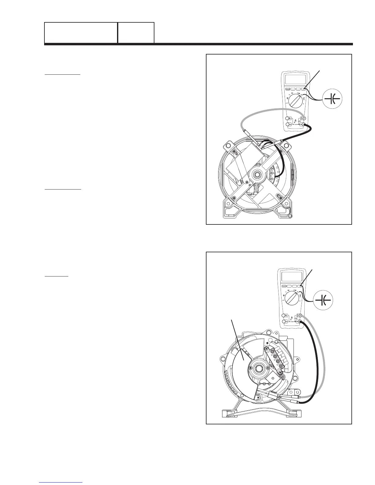
1. Consult the owner’s manual of the meter being used for
directions on measuring capacitance. Figures 7 and 8
show a typical meter and how to check capacitance.
2. Connect the meter leads directly across the terminals of
the capacitor. The rated µf (micro farad) of the capacitor
is marked on the side of the canister.
3. The meter should display the correct µf reading ± 5µf.
If anything other than the indicated rating is displayed,
replace the capacitor.
RESULTS:
1. Refer back to flow chart
2. Common observations can be made by visually inspect-
ing the capacitor.
a. A capacitor that has gone bad can have a ten-
dency to explode. Use caution when dealing
with an exploded capacitor, the gel from inside
a capacitor can cause skin irritation.
b. A capacitor is defective if the terminal connec-
tions are loose on the canister.
c. A capacitor is defective if it wobbles while sitting
on a flat surface.
d. If any of the above observations are observed,
replace the capacitor.
SET TO READ
CAPACITANCE
59.0
µf
Figure 7. Capacitor Test Points
(Alternator Configuration “A”)
SET TO READ
CAPACITANCE
28.0
µf
CAPACITOR 28µf
Figure 8. Capacitor Test Points
(Alternator Configuration “B”)
PART 2
Page 29

 Loading...


