AC GENERATORS
SECTION 2.3
AC DIAGNOSTIC TESTS
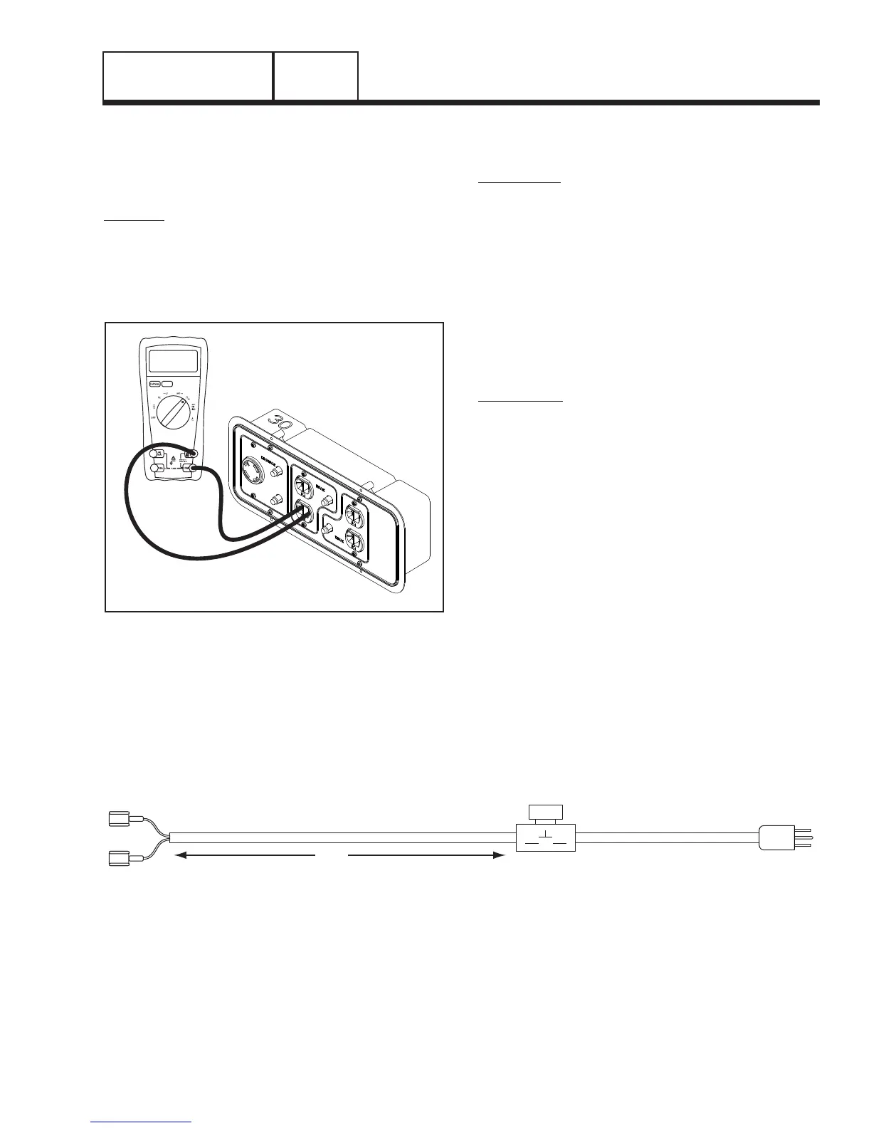
2. Connect a VOM as shown in Figure 3 to each receptacle
on the unit.
Note: Only one outlet on each receptacle needs to
be tested.
RESULTS:
1. If any other reading than continuity was measured fur-
ther troubleshooting will need to be done to determine if
it is the receptacle or the wiring.
2. If receptacles test good, refer back to flow chart.
Figure 3. Checking Continuity of Receptacles
TEST 4 – FIELD FLASH ALTERNATOR
(CONFIGURATION “A” ONLY)
DISCUSSION:
The alternator utilizes residual magnetism within the
windings to charge the capacitor. If the generator has
been sitting for a long period of time with no activity
the residual magnetism could be lost within the rotor.
Field flashing the rotor while connected in parallel with
the capacitor will force a charge of electricity through
the DPE winding. The voltage that is induced into the
rotor will in turn charge the rotor with enough residual
magnetism that it will be able to charge the capacitor
during normal operation.
*
Warning:
Please keep safety in mind while
performing this test.
PROCEDURE:
1. Construct an energizing cord that is similar to that shown
in Figure 4 and connect it as shown in Figure 5 on the
next page.
2. Set the START-RUN-STOP switch to the OFF position.
*
Warning:
Do NOT energize the capacitor for
more than 1 second at a time.
3. Momentarily turn on the energizing cord (one second).
4. Disconnect the energizing cord from the capacitor.
5.
If the field flash was successful, the generator should now
be producing approximately 240 VAC at the main circuit
breaker of the generator when the START-RUN-STOP is
set to the START position.
PART 2
Page 27
Figure 4. Construction of Energizing Cord
12 AWG12 AWG
MOMENTARY PUSHBUTTON ON/OFF SWITCH
SINGLE POLE SWITCH ON LIVE SIDE
DO NOT SUBSTITUTE ANY OTHER DEVICE
4 ft.
CRIMP ON STANDARD
FEMALE BLADE
CONNECTORS
STANDARD
MALE PLUG

 Loading...


