AC GENERATORS
SECTION 2.3
AC DIAGNOSTIC TESTS
TEST 9 – TEST BRUSHED STATOR WINDINGS
DISCUSSION:
Most brushed stators have three main windings that
are needed to produce voltage. The alternator has
two main power windings that supply power to the
load and a DPE winding to provide excitation voltage
to the rotor. It is important that these windings remain
isolated from ground or the chassis of the alternator.
PROCEDURE:
1. Isolate all stator wires from the control panel and the
voltage regulator.
2. Set a VOM to measure resistance.
3. Refer to Configuration “C” in Section 1.4 for proper test
points for checking the stator. Every connection needs to
be checked coming out of the stator for a short to ground.
RESULTS:
1. If any wire has a direct short to ground or to the chassis
of the alternator replace the alternator assembly.
2. If all wires test good for a short to ground, refer back to
flow chart.
TEST 10 – CHECK LOAD VOLTAGE &
FREQUENCY
PROCEDURE:
Perform this test in the same manner as Test 1, but
apply a load to the generator equal to its rated capacity.
With load applied check voltage and frequency.
Frequency should not drop below about 59 Hertz with
the load applied.
Voltage should not drop below about 220 VAC nor rise
above 265 VAC with load applied.
RESULTS:
1. If voltage and/or frequency drop excessively when the
load is applied, refer back to flow chart.
2. If load voltage and frequency are within limits, end tests.
TEST 11 – CHECK LOAD WATTS & AMPERAGE
PROCEDURE:
Add up the wattages or amperages of all loads pow-
ered by the generator at one time. If desired, a clamp-
on ammeter may be used to measure current flow.
See “Measuring Current” in Section 1.2.
A Wattage Reference Guide is provided on the next
page to assist in determining how many items the
generator can operate at one time.
NOTE: All figures are approximate. See data label
on appliance for wattage requirements.
RESULTS:
1. If the unit is overloaded, reduce the load.
2. If load is within limits, but frequency and voltage still drop
excessively, refer back to Flow Chart.
Overloading a generator in excess of its rated wattage
capacity can result in damage to the generator and to
connected electrical devices. Observe the following to
prevent overloading the unit:
• Addupthetotalwattageof allelectricaldevicesto
be connected at one time. This total should NOT be
greater than the generator's wattage capacity.
• Theratedwattageoflightscanbetakenfromlight
bulbs. The rated wattage of tools, appliances and
motors can usually be found on a data label or
decal affixed to the device.
• If the appliance, tool or motor does not give watt-
age, multiply volts times ampere rating to determine
watts (volts x amps = watts).
• Some electric motors, such as induction types,
require about three times more watts of power for
starting than for running. This surge of power lasts
only a few seconds when starting such motors.
Make sure to allow for high starting wattage when
selecting electrical devices to connect to the generator:
1. Figure the watts needed to start the largest motor.
2. Add to that figure the running watts of all other con-
nected loads.
TEST 12 – ADJUST VOLTAGE REGULATOR
PROCEDURE:
1. Remove cover from end of alternator assembly.
2. Remove two screws holding down the voltage regulator
(AVR); refer to Figure C in Section 1.4 for identification.
3. Leave AVR connected to stator and brushes
4. Set VOM to measure AC voltage.
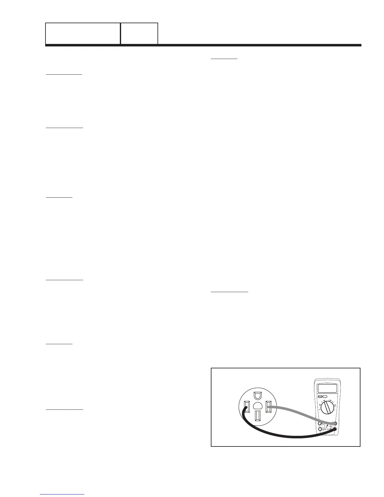
5. Connect VOM across a 240VAC socket as shown in
Figure 9.
Figure 9. VOM Test Leads Connected to a 240 VAC
receptacle
PART 2
Page 31

 Loading...


