Diagnostic Repair Manual 5
Section 2 Direct Excitation (Brush Type)
Introduction
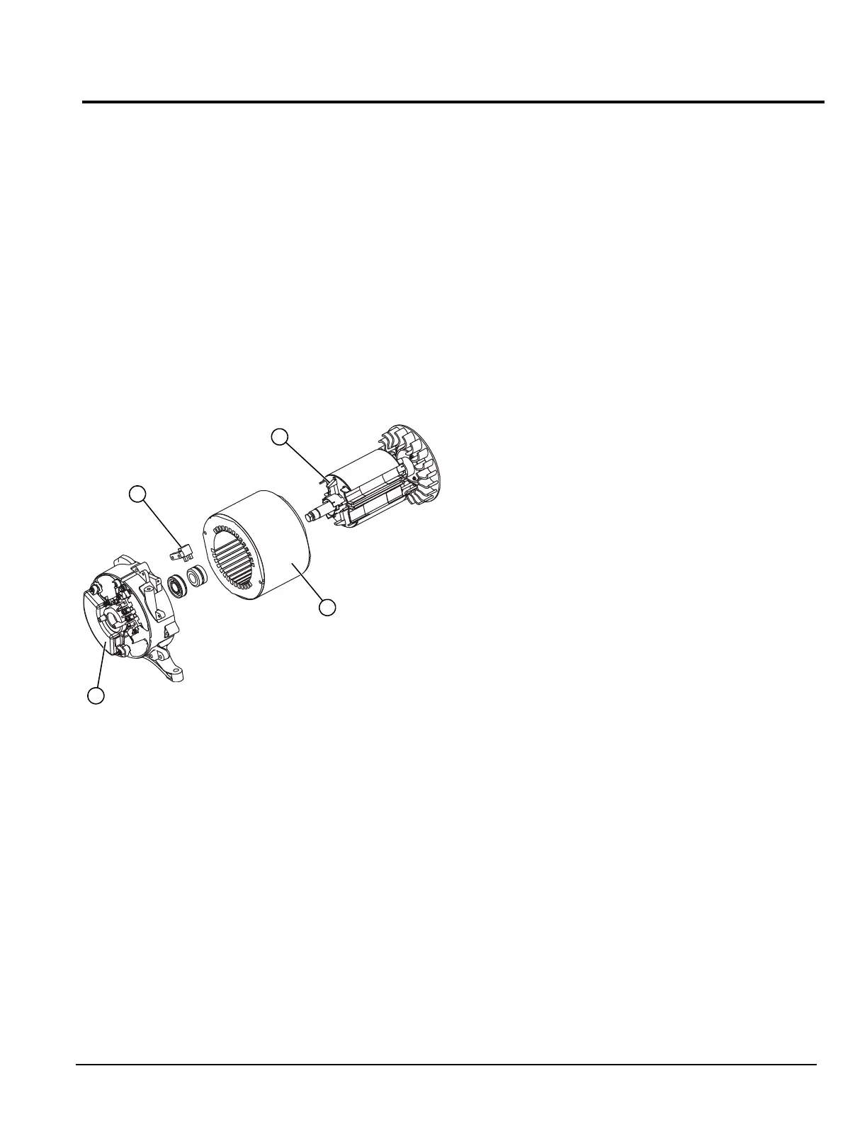
See Figure 2-1. A typical brush type portable generator
needs 4 major components to function: prime mover,
rotor, stator, and voltage regulator.
As the engine begins to rotate, residual magnetism from
the rotor creates magnetic lines of flux. The lines begin to
cut across the excitation winding and induce a small
voltage into the voltage regulator. The excitation voltage
will power the voltage regulator and the voltage regulator
will start to sense AC voltage from Wires S15 and S16.
The lower voltage from the sensing wires will cause DC
excitation to the rotor to be driven up until AC output is at
desired level of 240 VAC. Once the generator has
reached 240 VAC it will maintain the DC voltage,
regulating the alternator when loads are applied and
removed.
Figure 2-1. AC Generator Exploded View
Stator Assembly
The stator has three windings wound separately inside
the can. Two are the power windings and are located on
Wire 44 (Hot) and Wire 33 (Neutral); the other winding is
located on Wire 11 (Hot) and Wire 22 (neutral). The third
winding is called DPE winding or Displaced Phase
Excitation winding and is located on Wire 2 and Wire 6.
Some generators have color coded wires. Always use
the appropriate schematic and wiring diagram for unit.
Brush Holder and Brushes
The brush holder has a positive (+) and a negative (-)
brush, and is retained to the rear bearing carrier by
means of two Taptite screws. Wire 4 connects to the
positive (+) brush and Wire 0 to the negative (-) brush.
Rectified and regulated excitation current is delivered to
the rotor windings via Wire 4, and the positive (+) brush
and slip ring. The excitation current passes through the
windings to the negative (-) slip ring and brush on Wire 0.
This current flow creates a magnetic field around the rotor
having a flux concentration that is proportional to the
amount of current flow.
Voltage Regulator
See Figure 2-1. Unregulated AC output from the stator
excitation winding is delivered to the regulator’s DPE
terminals, via Wire 2 and Wire 6. The voltage regulator
rectifies that current and, based on stator AC power
winding sensing, regulates it. The rectified and regulated
excitation current is then delivered to the rotor windings
from the positive (+) and negative (-) regulator terminals,
via Wire 4 and Wire 0. Stator AC power winding “sensing”
is delivered to the regulator via Wires S15 and S16.
Operation
Startup
When the engine is started, residual magnetism from the
rotor induces a voltage into (a) the stator AC power
windings, (b) the stator excitation or DPE windings. In an
“on-speed” (engine cranking) condition, residual magnetism
is capable of creating approximately one to three volts AC.
On-Speed Operation
As the engine accelerates, the voltage that is induced
into the stator windings increases rapidly, due to the
increasing speed at which the rotor operates.
Field Excitation
An AC voltage is induced into the stator excitation (DPE)
windings. The DPE winding circuit is completed to the
voltage regulator, via Wire 2 and Wire 6. Unregulated
alternating current can flow from the winding to the
regulator. The voltage regulator senses AC power
winding output voltage and frequency via stator Wires
S15 and S16.
The regulator changes the AC from the excitation
winding to DC. In addition, based on the Wire S15 and
Wire S16 sensing signals, it regulates the flow of direct
current to the rotor. The rectified and regulated current
flow from the regulator is delivered to the rotor windings,
A. Rotor
B. Stator
C. Brushes
D. Voltage Regulator
A
B
C
D

 Loading...


