Section 5 Engine Diagnostic Tests
Diagnostic Repair Manual 35
Test 30 – Check / Adjust Governor
(220/410/530cc Non-EFI Engine)
The generator AC frequency output is directly
proportional to the speed of the rotor. A two-pole rotor
(having a single north and a single south magnetic pole)
will produce an AC frequency of 60 hertz at 3600 RPM.
The AC output voltage is generally proportional to AC
frequency. A low or high governor speed will result in a
correspondingly low or high AC frequency and voltage
output. The governed speed must be adjusted before any
attempt to adjust the voltage regulator is made.
Procedure
See Figure 5-21.
1. Loosen governor clamp bolt (A).
2. Hold governor lever (B) at its wide open throttle
position, and rotate governor shaft (C) clockwise as
far as it will go. Tighten governor lever clamp bolt
to 70 in-lbs (8 Nm).
3. Start generator and let stabilize and warm up at no-
load.
Figure 5-21. Governor Adjustment (410 Engine)
4. Connect a frequency meter across generator AC
output leads.
5. Turn primary adjust screw (D) to obtain a frequency
reading of 62.5 Hz.
6. When frequency is correct at no load, check AC
voltage reading. If voltage is incorrect, the voltage
regulator may require adjustment (if equipped).
Results
1. If after adjusting engine governor, frequency and
voltage are good, discontinue tests.
2. If frequency is good but voltage is high or low, refer
to flow chart.
3. If engine was overspeeding, check linkage and
throttle for binding. If no governor response is
indicated, refer to engine service manual.
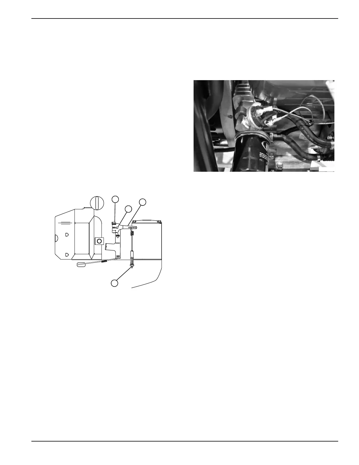
Test 31 – Check Oil Pressure Switch
If engine cranks and starts, then shuts down almost
immediately, check the following:
• Low engine oil level.
• Low oil pressure.
• Defective oil pressure switch.
Figure 5-22. Low Oil Pressure Switch
Procedure
1. Check engine crankcase oil level.
a. Check engine oil level.
b. If necessary, add recommended oil to di
pstick
FULL
mark. DO NOT OVERFILL
ABOVE
FULL
MARK.
2. Do the following:
a. Disconnect Wire 86 and Wire 0 from o
il
pressure s
witch te
rminals.
b.
Remove switch and install an oil pressu
re
ga
uge.
c. Start engine while observing oil pressure
reading on gauge.
d. Note oil pressure.
(1) Normal oil pressure is approximately 35-40
p
si with engine running. If normal oil pressure
is indicated, go to Step 4 of this test.
(2) If oil pressure is below about 10 psi, shut
engine down immediately. A problem
exists
i
n engine lubrication system. Refe
r to
Se
rvice Manual, Generac P/N 0F6923 fo
r
e
ngine service recommendations.
NOTE: The oil pressure switch is rated at 10 psi
for single cylinder engines.
3. Remove oil pressure gauge and install oil pressure
switch. Do NOT connect Wire 86 or Wire 0 to
switch terminals.
a. Set a DMM to measure resistance.
b. Connect meter test leads across switch
terminals. With engine shut down, the meter
should read CONTINUITY.
c. Crank and start engine. The meter should read
INFINITY.

 Loading...


