Section 5 Engine Diagnostic Tests
Diagnostic Repair Manual 33
Test 26 – Check Ignition Coil
General Theory
The ignition system used on these engines is a solid-
state (breakerless) type. The system utilizes a magnet on
the engine flywheel to induce a relatively low voltage into
an ignition coil assembly. Ignition coil internal
components increases voltage and delivers the high
voltage across spark plug gap.
The ignition coil houses a solid-state circuit board
controlling ignition timing. Timing is fixed, air gap is non-
adjustable, and spark advance is automatic.
Major components of the ignition system include (a)
ignition coil assembly, (b) spark plug, and (c) engine
flywheel.
Solid-state components encapsulated in ignition coil are
not accessible and cannot be serviced. If coil is defective,
replace assembly. The air gap between the coil and
flywheel magnet is fixed and non-adjustable.
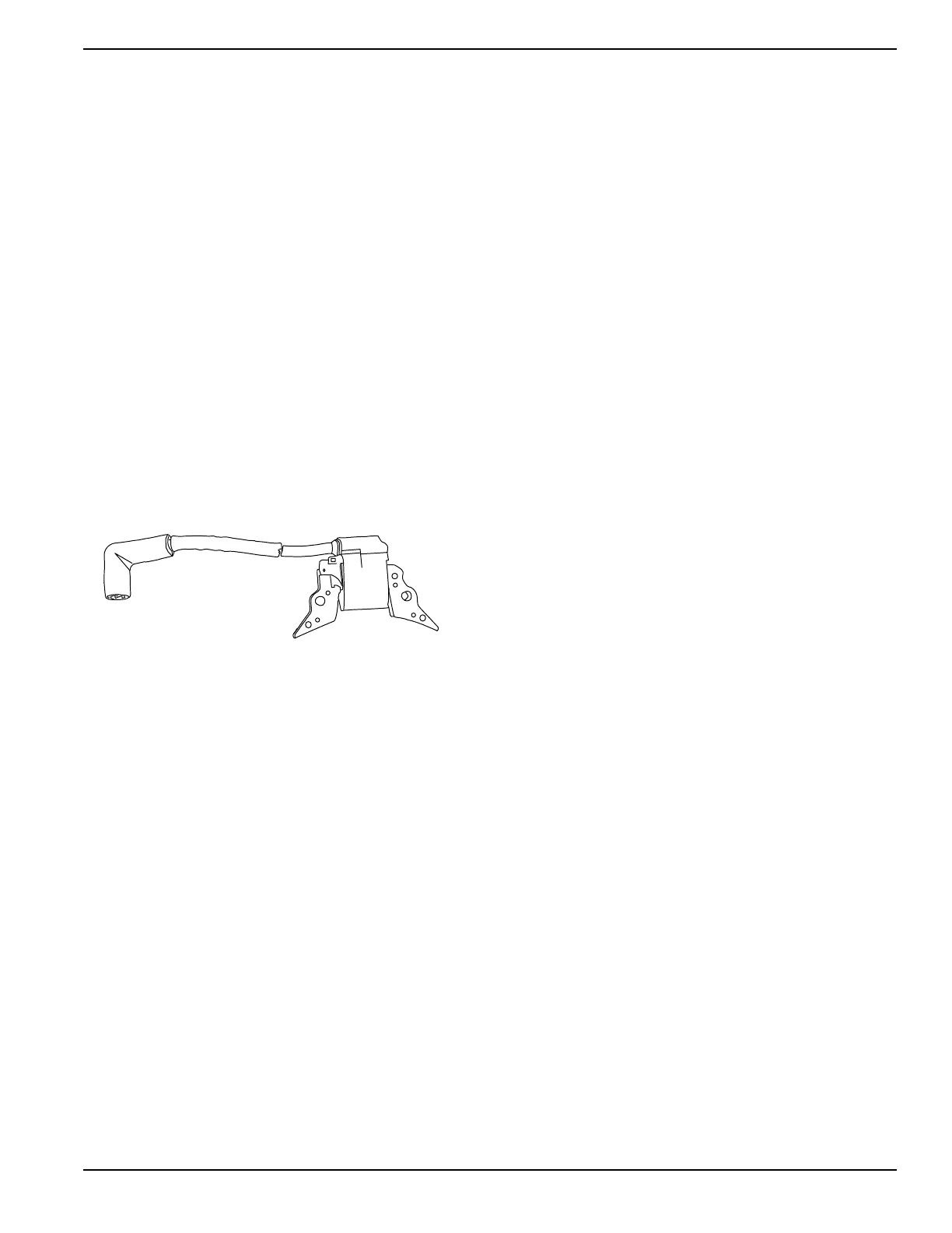
See Figure 5-17. The ignition coil assembly consists of
(a) ignition coil, (b) spark plug high tension lead, and (c)
spark plug boot.
Figure 5-17. Ignition Coil
Procedure
1. Disconnect Wire 18 at bullet connector and repeat
Test 20.
2. If unit produces spark, a short to ground exists on
Wire 18 between the Ignition Coil and RUN-STOP
switch.
3.
If unit still failed to produce spark, proceed to Step 4.
4. Set a DMM to measure resistance. Connect
negative (-) test lead to Wire 18, going to the coil.
Connect positive (+) test lead to frame ground.
Approximately 1.5 kΩ should be measured.
5.
Set a DMM to measure resistance. Disconnect high
tension lead from spark plug. Connect one test lead
to high tension lead. Connect other test lead to frame
ground. Approximately 16 kΩ should be measured.
Results
1. If unit was able to produce spark after
disconnecting Wire 18, a short to ground or a faulty
switch is supplying Wire 18 with a ground inhibiting
the engine from producing spark.
2. If Ignition Coil fails Step 4 or Step 5 by a high
margin, replace Ignition Coil.
3. If coil passes Step 4 and Step 5 but there is still no
spark, replace ignition co
il.
NOTE: Be
fore replacing ignition coil, check flywheel
magnet.
Checking Flywheel Magnet
The flywheel magnet rarely loses magnetism. To
determine if a magnet is be defective, perform this test:
1. Place flywheel on a wooden surface.
2. Hold a screwdriver at the utmost end of handle with
its point down.
3. Move tip of screwdriver to about 3/4 inch (19mm)
from magnet. The screwdriver blade should be
pulled in against magnet.
Flywheel Key
In all cases, the flywheel’s taper is locked on the
crankshaft taper by the torque of the flywheel nut. A
keyway is provided for alignment only and theoretically
carries no load.
If flywheel key becomes sheared or even partially
sheared, ignition timing can change. Incorrect timing can
result in hard starting or failure to start.
Test 27 – Check Flywheel
General Theory
See Figure 5-18. In Test 20, a spark tester was used to
check for engine ignition. If sparking or weak spark
occurred, a possible cause might be the ignition
magneto. This test checks magnetism of flywheel and will
check the flywheel key.
Procedure
1. Check flywheel magnet by holding a screwdriver at
extreme end of handle with its point down. When
the tip of screwdriver is moved to within 3/4 inch
(19mm) of magnet, the blade should be pulled in
against the magnet.
2. For rough running or hard starting engines, check
flywheel key. The flywheel’s taper is locked on the
crankshaft taper by the torque of the flywheel nut.
A keyway is provided for alignment only and
theoretically carries no load.
NOTE: If flywheel key becomes sheared or even partially
sheared, ignition timing can change. Incorrect timing can
result in hard starting or failure to start.

 Loading...


