Diagnostic Repair Manual 1
Section 1 Brushless Capacitor Excitation
Introduction
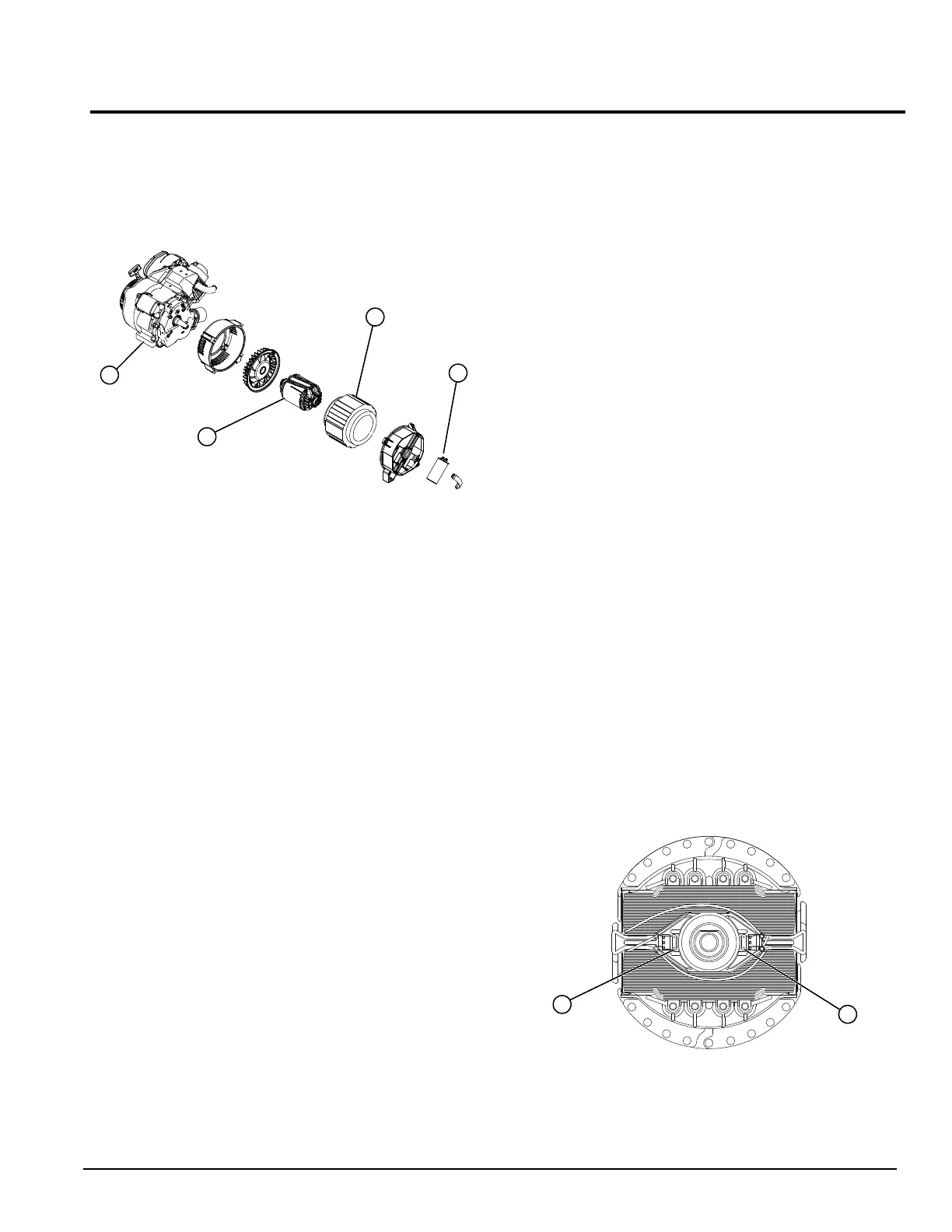
See Figure 1-1. A typical brushless type portable
generator needs 4 major components to function: a prime
mover, stator, rotor, and capacitor.
Figure 1-1. AC Generator Exploded View
As the engine begins to rotate, residual/permanent
magnetism from the rotor creates magnetic lines of flux.
The lines begin to cut the excitation winding and induce a
small voltage into the winding. The voltage causes the
capacitor to charge.
The capacitor on the excitation winding takes the place of
a voltage regulator. It will charge until AC peaks, then as
AC starts to fade it will discharge causing a voltage to be
induced into the rotor.
In one rotation of the rotor, the capacitor will charge and
discharge twice. Because it's being charged by the North
and South poles, it will induce AC voltage discharges into
the rotor.
Two diodes in the rotor convert AC voltage to DC. There
is a diode in one pole that is orientated in one direction,
and a diode in the opposite pole orientated in the
opposite direction. This produces a North and South
poled rotor.
A capacitor discharge generator will produce a lower
voltage until load is applied. Once load is applied, the
output voltage will rise due to induction into the DPE
Winding/Capacitor.
As load is applied, current in the main AC windings
increases. This increase in EMF is also induced into the
excitation winding (much like a transformer functions).
The increased EMF into the excitation winding causes
voltage to increase which also increases the charge/
discharge value of the capacitor. This creates a stronger
magnetic field in the rotor and higher AC output.
NOTE: This will only increase from no load to full load
and will stop increasing at that point.
NOTE: The voltage of a brushless capacitive discharge
generator will start low and increase as load is applied.
Stator Assembly
The stator has three windings wound separately inside
the can. Two are power windings located on Wire 44
(Hot) and Wire 33 (Neutral), the other winding is on Wire
11 (Hot) and Wire 22 (Neutral). The third winding is the
Displaced Phase Excitation (DPE) winding and is on
Wire 2 and Wire 6. Some generators have color coded
wires. Always use the appropriate schematic and wiring
diagram for unit.
Rotor Assembly
See Figure 1-2. The 2-pole rotor must be operated at
3600 rpm to supply a 60 Hertz AC frequency. The term
“2-pole” means the rotor has a single north magnetic pole
and a single south magnetic pole. It spins freely inside
the stator can and is excited by the charging and
discharging of the capacitor. It has two diodes (A and B)
that rectify voltage induced from the Excitation winding to
DC voltage. Each winding/pole will have a diode
orientated to create current flow in one direction, and the
other winding/pole will have a diode orientated to create
current flow in the opposite direction. This creates a
North and South pole. The rotor bearing is pressed onto
the end of the rotor shaft. The tapered rotor shaft is
mounted to a tapered crankshaft and is held in place with
a single through bolt.
NOTE: Some Rotors have a magnet placed inside the
laminations to help excite the rotor after it's been left idle
for a long period of time.
Figure 1-2. Rotor and Diodes
A. Engine
B. Rotor
C. Stator
D. Capacitor
A
B
C
D
004967

 Loading...


