Section 5 Engine Diagnostic Tests
36 Diagnostic Repair Manual
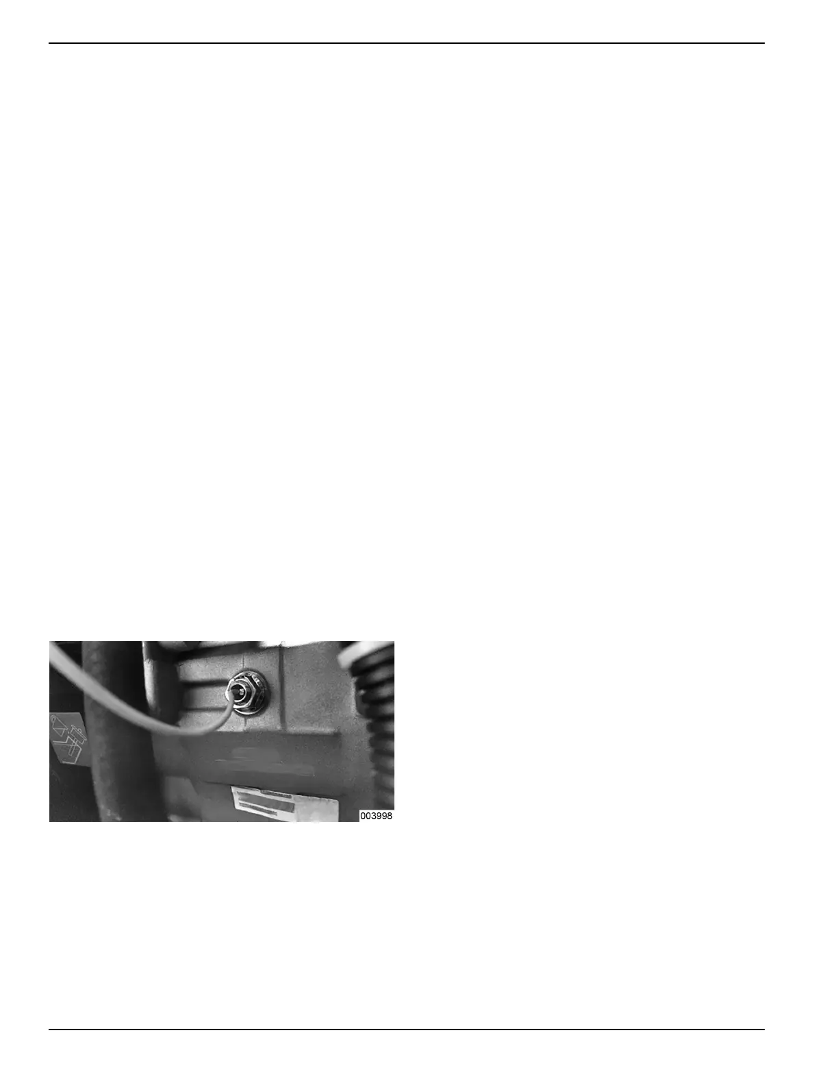
d. Connect one test lead to Wire 0 (disconnected
from LOP). Connect the other test lead to a clean
frame ground. CONTINUITY should be
measured. If CONTINUITY is NOT measured
repair or replace Wire 0 between the LOP and
the ground terminal connection on engine mount.
4. If LOP switch tests good in Step 3 and oil pressure
is good in Step 2 but unit still shuts down with a
LOP fault, check all wiring connections between
START-STOP-RUN switch and LOP pressure
module and LOP sender for a short to ground. Any
ground on this wire will cause Wire 18 to receive a
ground, also inhibiting spark from occurring. If a
short to ground is found, replace wire.
Results
1. If LOP switch, oil pressure, and wiring all test good,
refer to flow chart.
2. If LOP switch failed, replace switch.
3. If no pressure was measured, an internal failure of
oil pump may have occurred.
Test 32 – Check Oil Level Switch
General Theory
Some engines utilizes a splash type lubrication system.
The switch should be open when the engine is filled with
oil. The switch will close when the oil level drops too low.
The switch will close and ground out the magnetos
inhibiting spark until the oil level is raised.
Procedure
1. Verify the oil level is full.
2. Unplug wire from oil level switch.
Figure 5-23. Oil Level Switch
3. Set DMM to measure resistance.
4. Connect one meter test lead to disconnected wire
from oil level switch. Connect the other meter test
lead to frame ground. INFINITY should be
measured.
Results
1. A CONTINUITY reading indicates the switch is not
functioning. Replace switch.
Test 33 – Test Recoil Function
Procedure
1. Attempt to pull start engine and observe the
following:
a. Does cord pull easily and smoothly?
b. Does cord return with no assistance?
c. Does engine turn over as cord is pulled?
Results
If recoil did not perform correctly, possible problems
could be:
• Compression release valve on 410 engine could
be broken.
• Engine could be seized.
• Recoil could have become detached from flywheel.
• Recoil mechanism could be broken and not
properly retracting back into engine.
Test 34 – Test Engine Function
Procedure
1. Remove recoil and front cover assembly.
2. Remove spark plug from unit.
3. Attempt to turn engine over by hand.
Results
1. If engine cannot turn over freely with spark plug
removed, the engine has suffered an internal
failure and seized.
2. Refer to flow chart.
Test 35 – Test Battery Charger (Non-
EFI Units)
General Theory
The battery will not charge when the generator is
running.
Some generators are equipped with a battery charger to
charge the battery when the generator is running. There
is a 120 VAC “wall” charger that comes with the
generator to plug into a 120 VAC outlet to charge the
battery when the generator is not running.
1. Check power to the AC charger at the outlet. If
voltage is not present try another outlet. If voltage
is present move to step 2.
2. Check voltage at the external battery charger
connection in side of the control panel. Remove
Wire 13 a from F1 fuse holder.
3. Set DMM to read DC volts and place the positive
lead on Wire 13A and the negative lead to the
control panel ground. The voltage should be 13.5

 Loading...


