Section 5 Engine Diagnostic Tests
34 Diagnostic Repair Manual
Figure 5-18. Engine Ground Harness
Test 28 – Remove Shutdown Wire
General Theory
Wire 18 on all engines is used to shut down the unit when
either the switch is placed in OFF, or a low oil condition
occurred. A ground is applied to the magneto in both
instances which inhibits spark and shuts down unit. If a
short to ground exists on this wire, the engine will be
inhibited from producing spark. This test will check the
integrity of the wire.
Procedure
1. Turn off fuel supply.
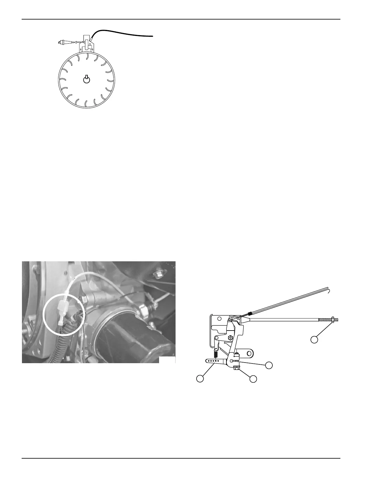
2. Remove flywheel cover so magneto is exposed.
3. See Figure 5-19. Disconnect Wire 18 from
magneto.
4. Repeat Test 20 – Check Ignition Spark.
Figure 5-19. Wire 18 (410 Engine)
Results
1. If spark now occurs, Wire 18 has a short to ground.
Trace Wire 18 back to START-RUN-STOP switch
and Oil Pressure Module (if equipped).
2. If spark still does not occur, refer to flow chart.
Test 29 – Check / Adjust Governor
(208/389/420cc Non-EFI Engine)
Rotor operating speed and AC output frequency are
proportional. The generator delivers a frequency of 60
Hertz at 3600 Rotor rpm or 62 Hertz at 3720 Rotor rpm.
The Voltage Regulator should be adjusted to deliver 120
VAC (line-to-neutral) at a frequency of 60 Hertz or 124
VAC (line-to-neutral at 62 Hertz. It is apparent if governed
speed is high or low, AC frequency and voltage will be
correspondingly high or low. Governed speed at no-load
is usually set slightly above rated speed of 60 Hertz (to
62 Hertz) to prevent excessive rpm, frequency, and
voltage droop under heavy electrical loading.
Procedure
See Figure 5-20.
1. Loosen governor clamp bolt (A).
2. Push Spring end of governor lever (B) clockwise to
wide open throttle position.
a. Hold governor lever at wide open throttle an
d,
with
a pair of pliers, rotate governor shaft (C
)
fully c
lockwise (CW). Use minimum amount
of
fo
rce against governor shaft.
b. While holding governor shaft fully clockwis
e
an
d the governor lever at wide open thro
ttle,
tighte
n governor clamp bolt (A) to 70 inch-
pounds (8 Nm).
3. Start engine. Let stabilize and warm up at no-load.
4. Turn adjuster nut (D) to obtain frequency reading of
62 Hertz.
5. Determine if governor spring is properly located in
slot of governor lever.
Figure 5-20. Governor Adjustment (220/410 Engine)
6. After repositioning spring on lever slot, check
frequency reading and, if necessary, adjust
adjuster nut to obtain 62 Hertz at no-load.
7. When frequency is correct at no-load, check AC
voltage reading. If voltage is incorrect, the voltage
regulator may require adjustment. See Test 12 –
Adjust Voltage Regulator.

 Loading...


