Section 5 Engine Diagnostic Tests
Diagnostic Repair Manual 27
Introduction
Perform the Diagnostic Tests in this section in
conjunction with the Diagnostic Flow Charts. Test
numbers in this chapter correspond to numbered tests in
the flow charts.
NOTE: Test procedures in this manual are not
necessarily the only methods for diagnosing the condition
of components and circuits. All possible methods that
might be used for system diagnosis have not been
evaluated. If any diagnostic method is used other than
the method presented in this manual, the technician must
be sure that neither personal safety nor product safety,
will be endangered by the procedure or method selected.
Test 14 – Check Fuse
General Theory
See Figure 5-1. The fuse protects the wiring and battery
charger from a short circuit.
Procedure
Push in fuse holder cap and turn counterclockwise.
Remove cap with fuse. Inspect fuse.
Results
If fuse element melted open, replace fuse with an
identical size fuse. If fuse is good, refer to flow chart.
Figure 5-1. Typical Fuse
NOTE: Fuse may be an in-line wire style.
Test 15 – Check Battery and Cables
General Theory
Battery power is used to (a) crank the engine and (b) to
power the circuit board. Low or no battery voltage can
result in failure of the engine to crank.
The battery charging circuit is not designed to recharge a
dead battery. As well, if there is a loose connection or
corrosion associated with a wire (positive or negative),
battery voltage may be present, but due to high
resistance, will not allow current to flow.
Electrical voltage drop varies according to current flow.
Voltage drop cannot be measured unless the circuit is
operated so current can flow through it. A crank attempt
will need to be performed to properly measure voltage
drop. This test will determine whether the battery, battery
cables, or both are at fault.
Procedure A – Perform Starter Circuit Voltage
Drop Test
1. Set a digital multimeter (DMM) to measure DC volt-
ag
e.
2. Connect the red meter test lead to the positive
battery post and connect the black meter test lead
to the negative battery po
st.
a.
If battery voltage is 12.1 VDC or below
,
r
echarge the battery and rete
st.
b.
If battery voltage is 12.2 VDC or abo
ve,
pr
oceed to next step. (For this test, battery
voltage should be at leas
t 12.2 VDC)
3. To inhibit any possible startup, turn off the fuel
source and ground the ignition control wire. (refer
to applicable schematic)
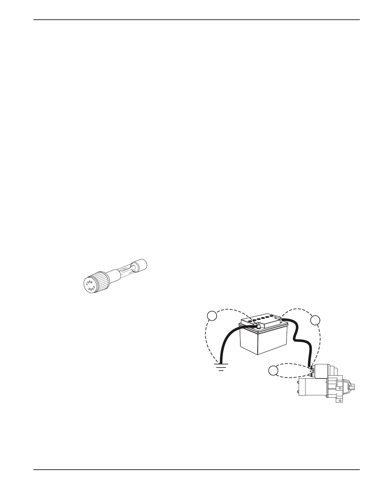
4. Refer to battery post and starter connections in
Figure 5-2 and Figure 5-3 then perform a voltage
drop test as indicated.
5. Set the start-run-stop switch to START. Allow the
engine to crank long enough to obtain a steady
measurement.
6. Record voltage readings from test points V1, V2,
V3 and V4. Although resistance-free connections,
wires and cables would be ideal, most of them will
contain at least some voltage drop. The maximum
voltage readings should be as follows:
a. 0.00-0.10 VDC across a connection or batter
y
post (V4).
b. 0.10-0.20 VDC on a ground connection.
c. 0.20-0.30 VDC across a wire or cable (V1, V2).
d. 0.20-0.30 VDC across a switch or starter
contactor (V3).
e. 0.40-0.50 VDC across the entire circui
t
F
igure 5-2. Starter Circuit Voltage Drop Te
st
Con
nections

 Loading...


