GMV5 D.C INVERTER MULTI VRF SERVICE MANUAL
204
3.2 COMPRESSOR REPLACEMENT AND CAUTIONS
3.2.1 Determining Compressor Fault
3.2.1.1 Precondition: Units can be normally started.
Step 1:
If units can be normally started, start the units so as to measure line current of the faulty compressor.
Use a pressure gauge to measure pressure of various valves and connect the gauge to a PC for viewing
test data. Verify the current data in the figures below against the current recommended. For inverter
compressors, current will be deviated 10% while rate of turn and operating condition vary.
(
1
)
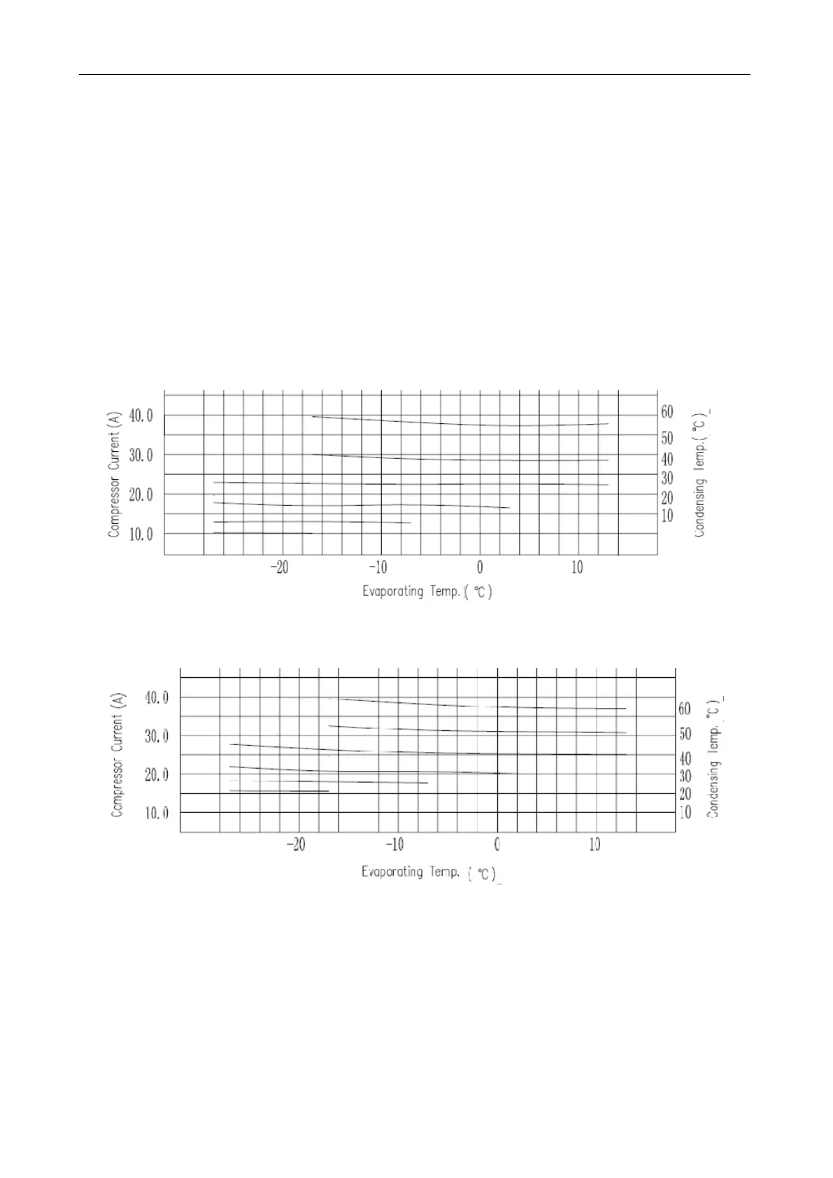
For inverter compressors E706DHD-72A2YG:
The figure below shows current curves that change with evaporating temperature and condensing
temperature while the compressors work at 30 Hz.
The figure below shows current curves that change with evaporating temperature and condensing
temperature while the compressors work at 60 Hz.
The figure below shows current curves that change with evaporating temperature and condensing
temperature while the compressors work at 90 Hz.
 Loading...


