GMV5 D.C INVERTER MULTI VRF SERVICE MANUAL
268
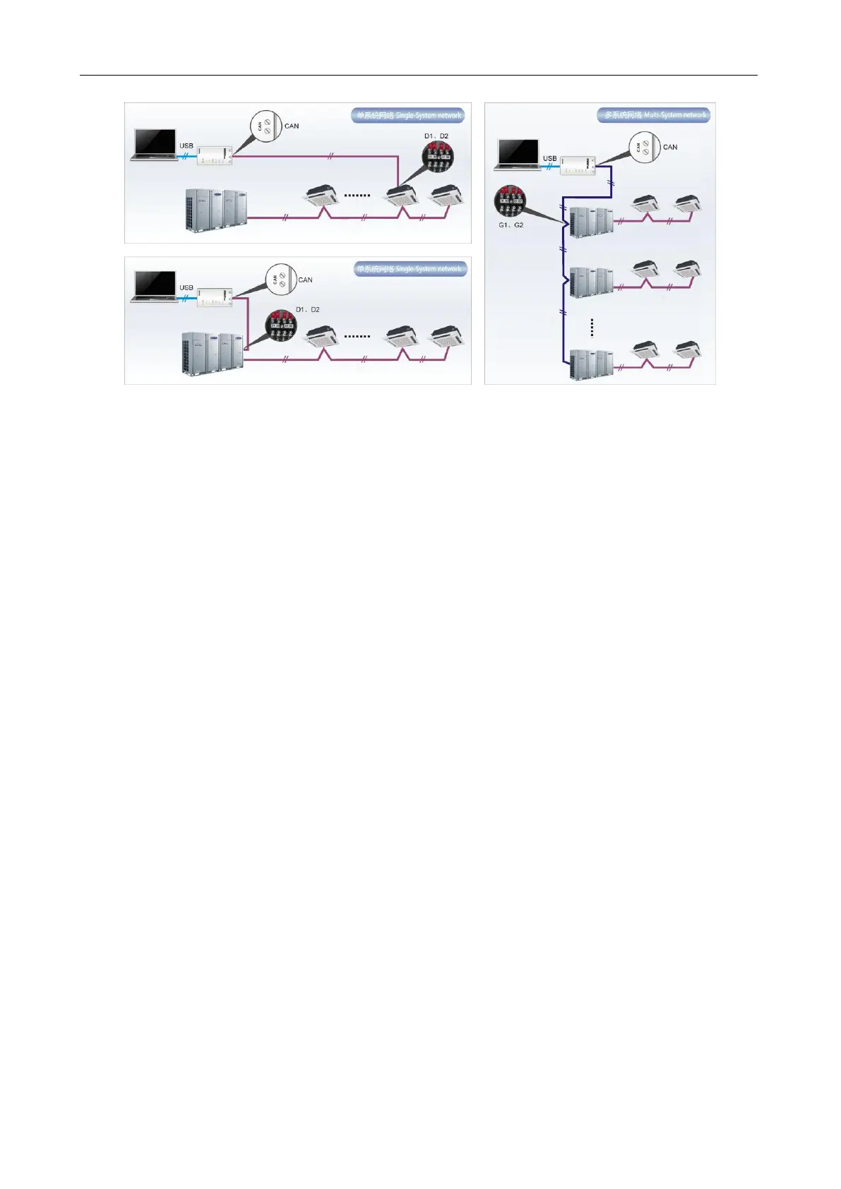
1.2 System Networking
Gree Debugger is applicable to both single-system network and multi-system network. In a
single-system network, the software can control both IDUs and ODUs. In a multi-system network,
however, the software can control the master ODU only.
1.2.1 Composition of System Network
From the network topology, it can be seen that Gree debugging network is composed of three parts:
Control PC part in the monitor room, including Gree Debugger and USB Converter Driver installed
in the PCs.
USB data conversion part, mainly converts air conditioning units' communication mode into PC
recognizable mode. Devices include USB data converters and USB data lines.
Air conditioning unit part, mainly composed of air conditioning units, including ODUs, IDUs, and
lines. If the lines are not long enough, the transfer board accompanied with Gree Debugger can help
connect the lines together. In a single-system network, the converter can be connected to an IDU or an
ODU. In a multi-system network, however, the converter can be connected to a master ODU only.
 Loading...


