GMV5 D.C INVERTER MULTI VRF SERVICE MANUAL
233
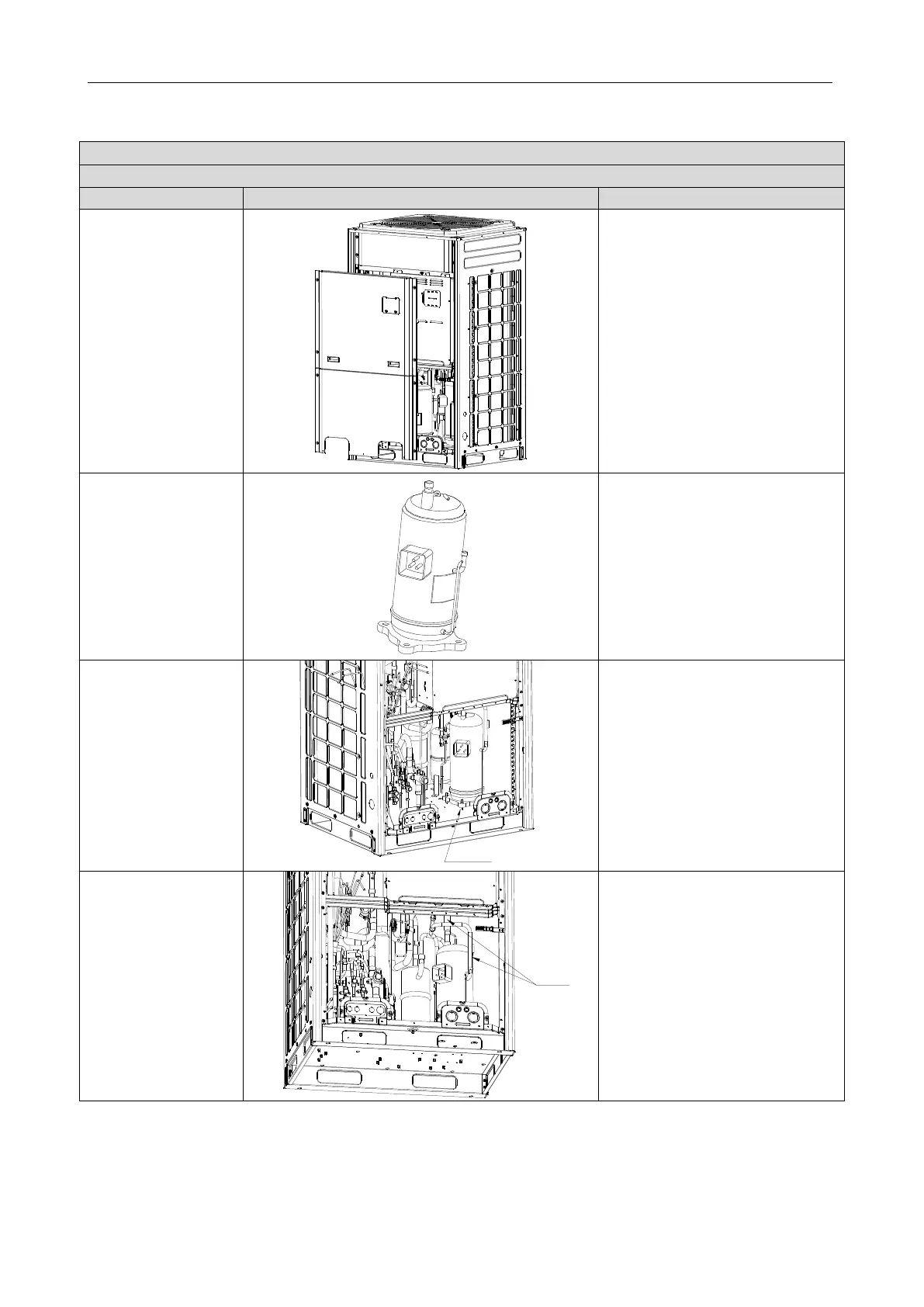
3.4 ASSEMBLING AND DISASSEMBLING KEY PARTS OF ODUS
Precondition: No refrigerant exists in the pipeline system and the power supply has been disconnected.
1. Remove the front
panels.
●Use a screwdriver to unscrew the
upper and lower front panels.
●Lift the front panels in order to take
it out.
Note: Both the upper panel and lower
panel are fixed with two fasteners
respectively to connect to the side
panels.
2. Disconnect the
power line of the
compressor, and
remove the electric
heating belt, top
temperature sensor,
and discharge air
temperature sensor.
●Remove the sound-proof sponge
from the compressor.
●
Use a screwdriver to unscrew the
power line.
●
Remove the power line.
●Remove the electric heating belt,
top temperature sensor, and
discharge air temperature sensor.
Note: Before removing the power
line, mark the colours of the line and
corresponding wiring terminals.
3. Loosen the nuts of
the compressor.
●Use a wrench to unscrew the four
nuts.
4. Remove the suction
and discharge pipes.
●Heat the suction and discharge
pipes by acetylene welding and then
remove the pipes.
●
During welding, charge nitrogen
into the pipes. The pressure should
be controlled within 0.5±0.1 kgf/cm
2
(relative pressure).
●
Avoid nearby materials from being
burnt during welding.
 Loading...


