80DWFK6HULHV'&
,QYHUWHU6HUYLFH0DQXDO
78
Ɣ
For air-conditioner with auxiliary heater, it is required to connect the power cable to the “L1, L2
/´WHUPLQDOVDQGWKHJURXQGLQJVFUHZ
4.1.4 Connection of Signal Line of Wire Controller
Caution:
Take great care when carrying out the following connections, so as to avoid malfunction of the air-
conditioning unit because of electromagnetic interference.
The signal line of the wire controller must be separated from the power line and the connecting line
between the indoor unit and the outdoor unit.
In case the unit is installed in a place vulnerable by electromagnetic interference, it is better to use
shielded cable or double-twisted cable as the signal line of the wire controller.
Open the cover of the electric box of the indoor unit.
Pull the signal cable of the wire controller through the rubber ring.
Plug the signal line of the wire controller onto the 4-bit pin socket at the circuit board of the indoor unit.
8VHFDEOHIDVWHQHUWREXQGOHDQG¿[WKHVLJQDOFDEOHRIWKHZLUHFRQWUROOHU
4.1.5 Cable Connection
Remove the right side plate of the indoor unit and punch through the cable-cross hole. Mount the cable-
cross loop.
5HPRYHWKHFDEOHFODPS&RQQHFWWKHSRZHUFDEOHWRWKHWHUPLQDODQG¿[LW
Fix the power cable and signal control wire with cable clamp. Then, connect to corresponding connector
properly.
&RQ¿UPLIWKHFDEOHVDUHVHFXUHO\¿[HG
Mount the front side plate.
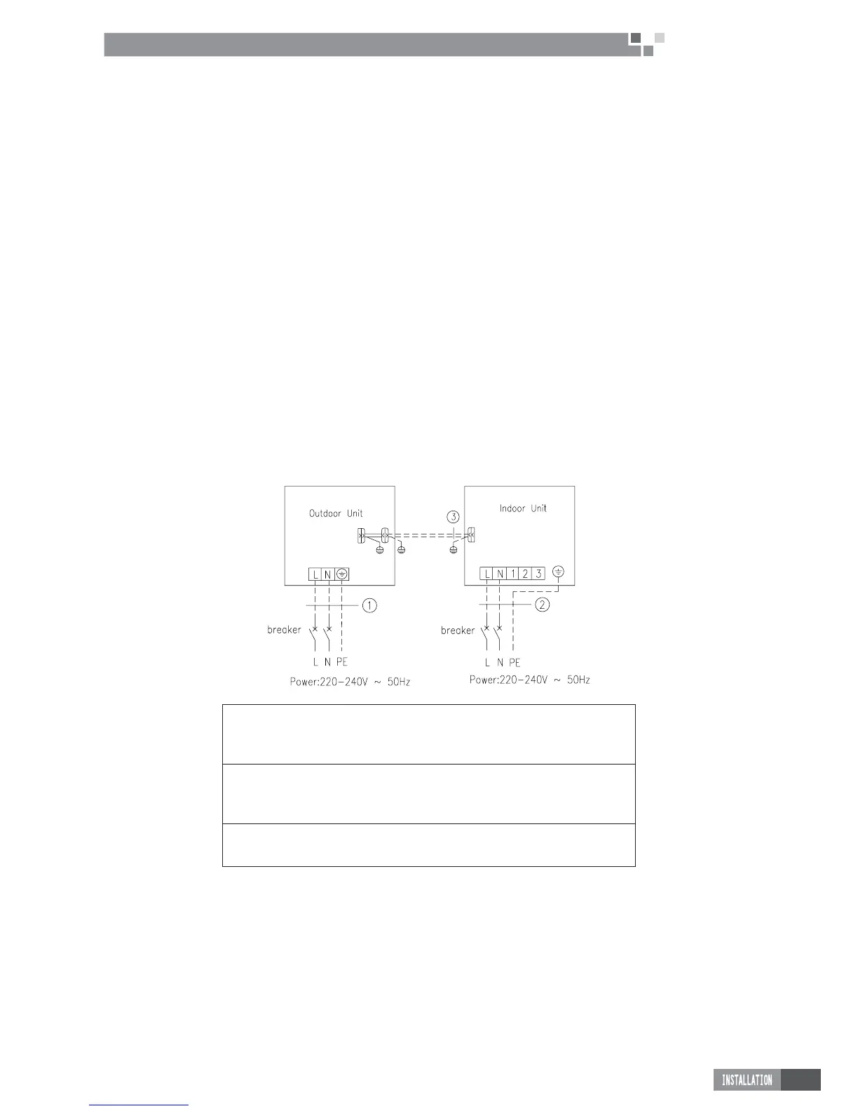
4.2 Electric Wiring Design
GUHD09NK3CO / GUHD09NK3C1O + GFH09K3CI
GUHD12NK3CO / GUHD12NK3C1O + GFH12K3CI
1. Power cord 3×2.5 mm
2
(H07RN-F) 2. Power cord 3×1.0 mm
2
(H05VV-F)
3. Communication Cords
GUHD36NK3CO/ GUHD36NK3C1O + GFH36K3CI
GUHD42NK3CO/ GUHD42NK3C1O + GFH42K3CI
1.Power cord 3×4.0 mm
2
(H07RN-F) 2.Power cord 3×1.0 mm
2
(H05VV-F)
3.Communication Cords
GUHD48NK3CO/ GUHD48NK3C1O + GFH48K3CI
1.Power cord 3×6.0 mm
2
(H07RN-F) 2.Power cord 3×1.0mm
2
(H05VV-F)
3.Communication Cords
 Loading...