80DWFK6HULHV'&
,QYHUWHU6HUYLFH0DQXDO
75
Ɣ
Use adhesive tape to bundle the connecting pipe and the cables together. To prevent condensate
IURPRYHUÀRZLQJRXWIURPWKHGUDLQDJHSLSHVHSDUDWHWKHGUDLQDJHSLSH¿UPWKHFRQQHFWLQJSLSHDQGWKH
cables.
Ɣ
Use thermal insulation tape to wrap the pipes from the bottom of the outdoor unit until the upper end
of the pipe where the pipe enters the wall. When wrapping thermal insulation tape, the later circle of tape
must cover half of the front circle of tape (Figure 3-1-7).
Ɣ
:UDSSHGSLSHPXVWEH¿[HGWRZDOOXVLQJSLSHFODPSV
Caution:
After the pipes are wrapped by protective materials, never bend the pipes to form very small angle, and
otherwise the pipes may crack or break.
Do not wrap the protective tape too tight, otherwise the efficiency of thermal insulation may be
GHFUHDVHG(QVXUHWKDWWKHFRQGHQVDWHGUDLQDJHÀH[LEOHWXEHLVVHSDUDWHIURPWKHEXQGOHGSLSHV
After the protective work is completed and the pipes are wrapped, use seal material to block the hole in
the wall, so as to prevent rain and wind from entering the room.
3.2 Caution in Connecting Pipes
The layout of connection pipes shall be in reference to the following principles according to site
conditions:
Shorten the connection pipe to minimum, preferably within 5m.
Reduce the height difference between indoor and outdoor units as it might be.
Minimize the number of elbows on connection pipe.
If the connection pipe is longer than 20m, it is needed to check if the lubricating oil in the system is
enough. Add if needed.
The refrigerant charge volume inside the machine is suitable for 7m connection pipe. To extend the
length of connection pipe, it is needed to add an appropriate quantity of refrigerant. For extension of pipe
length by every 1 meter, the refrigerant to be added is as follows. The maximum allowable length of pipe is
as follows.
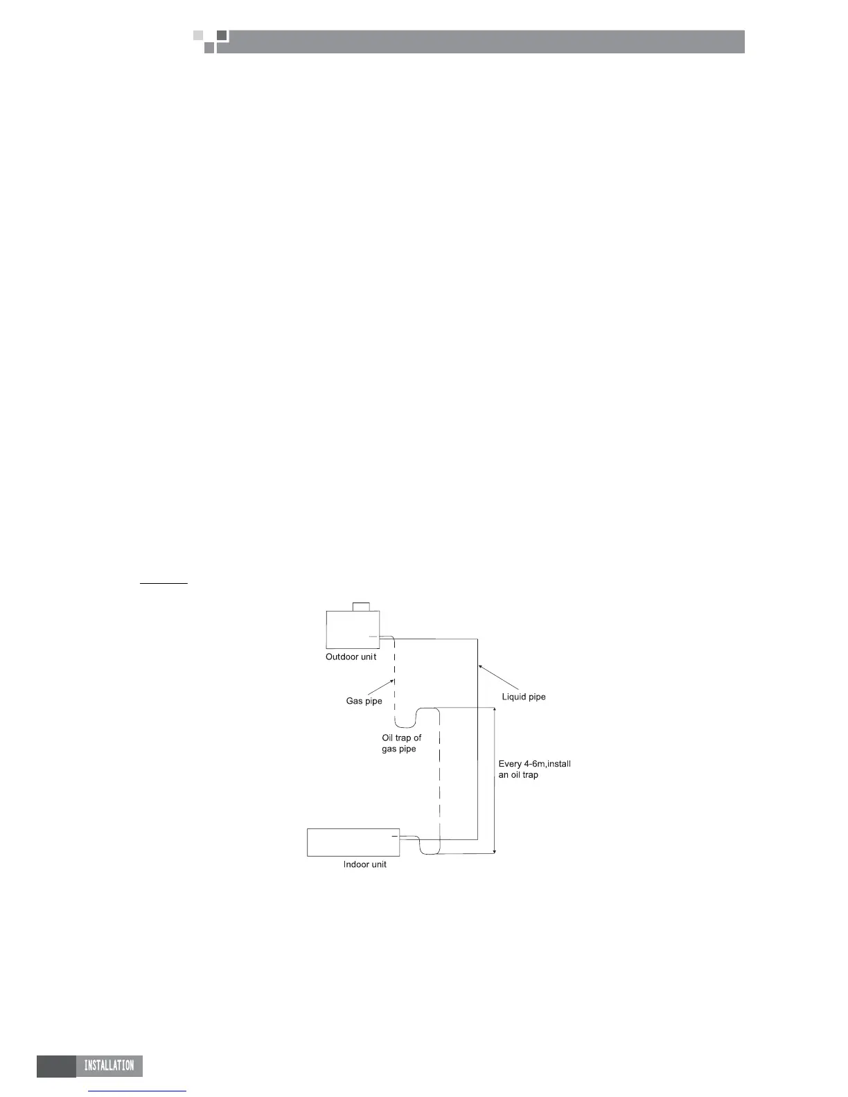
If the height difference between indoor and outdoor units is over 10m, it is required to install an oil trap
every 6 meters.
When the indoor and outdoor units are on different height, please refer to Fig. 30201 for pipe layout.
/LTXLGSLSHLH¿QHSLSH
- - - - - - Gas pipe (i.e. coarse pipe)
Figure 3-2-1
 Loading...