4.4.1 Preparation at the site
Before installing a controller, prepare the following items.
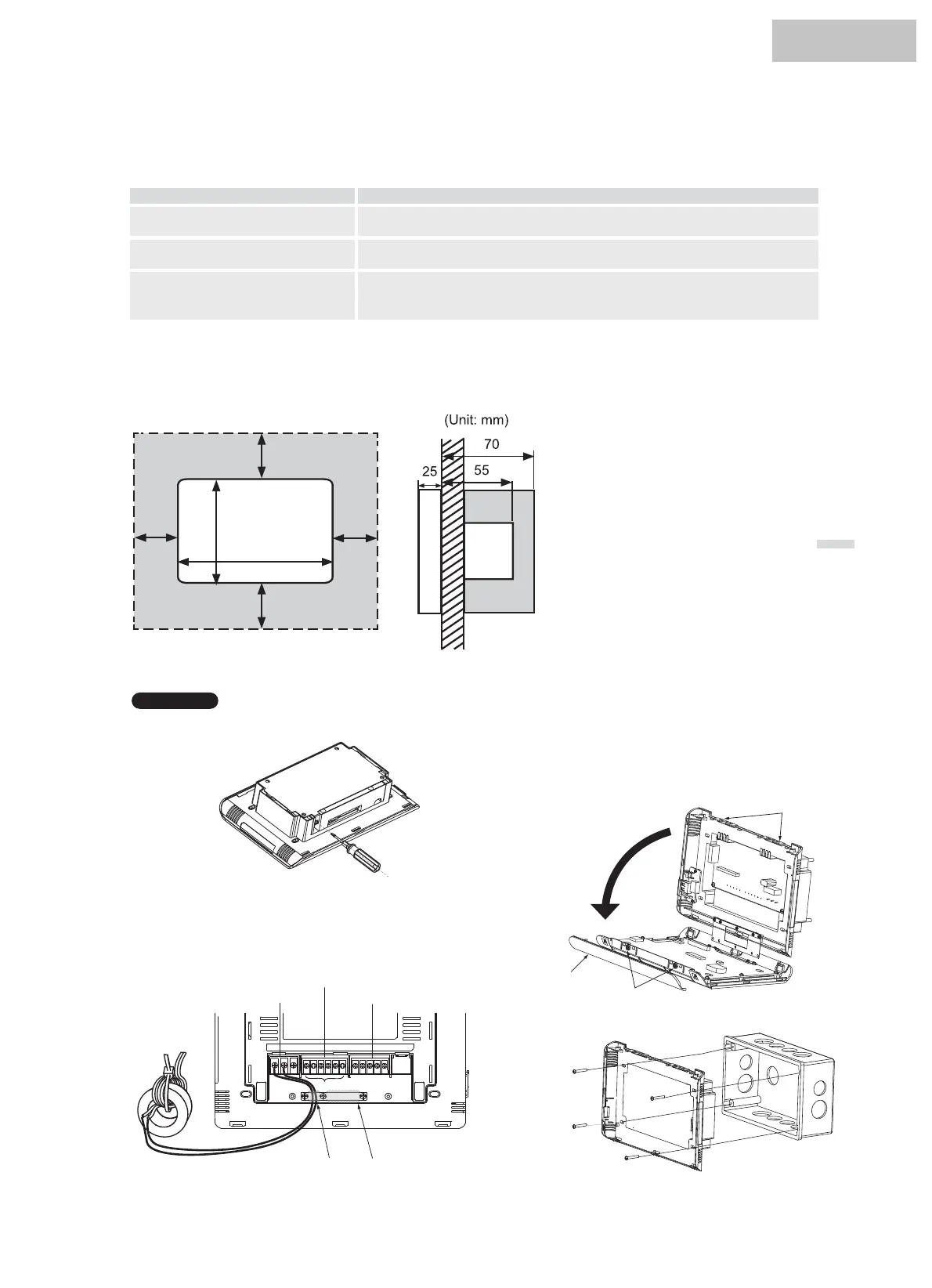
4.4.2 Installation space
Keep the installation space for the central controller as shown below.
Parts
Switch Box
Power Supply Cable
H-NET Cable (For Control)
Specification
Switch Box for 7” touchscreen(non-essential for Wall Surface Mouting)
Cable SPEC: 0.75 mm
2
Recommended Cable: 600V CV, CCV, CEV
Cable SPEC: 0.75 mm
2
Recommended Cable:Twist Pair Cable with Shield,
Over 0.75 mm
2
100
100
148
100
220
100
Do not attach anything in the halftone screen area .
When installing central controller near other devices in row
or in line, keep the space between each.
* Vertical Direction: 100mm
* Horizontal Direction: 100mm
7. Fix the switch box by accessory fixing screw (M3 x 20mm).
4.4.3 Installation method
1. Install the switch box into the wall.
2. Take off the rack as shown.
3. Open the terminal cover, and connect the wring to the
terminal of controller.
6. Open the unit body as shown below.
a. Open the top cover of unit body.
b. While pressing the convex part (2 portions), pull the
top case and the controller opened .
4. When the connection is finished, the strong and weak
wires are separated by a press plate and fixed as illustrated.
5. Cover the rear cover and fix the cover with 2 screws
(M3x 6mm)。
Wall Built-in:
')d< .4+:Non-pole
Terminals for external input/output
a. The power cable is wound around the magnet ring 3 times
and finally the cable and magnet ring are fixed with tie band.
b. The external input and output signal wires are respectively
connected to the corresponding terminals.
.OMN<URZGMK2OTK'XKG =KGQ\URZGMKROTKGXKG
Catch for fixing
Top cover
Convex part
HYJM-S01H
 Loading...