11-3
1
2
3
4
5
6
7
8
9
10
11
12
13
14
15
16
17
18
19
20
2. GEAR CASE ASSEMBLY/
EXTENSION SEPARATOR
[SEMI-LONG/EXTRA-LONG SHAFT
TYPES ONLY]
a. REMOVAL
1) Remove the propeller (P. 11-2).
2) Move the shift to the "N" (Neutral) position.
3) Tilt the outboard motor up to the uppermost position. Pull
the tilt stopper down to secure the outboard motor.
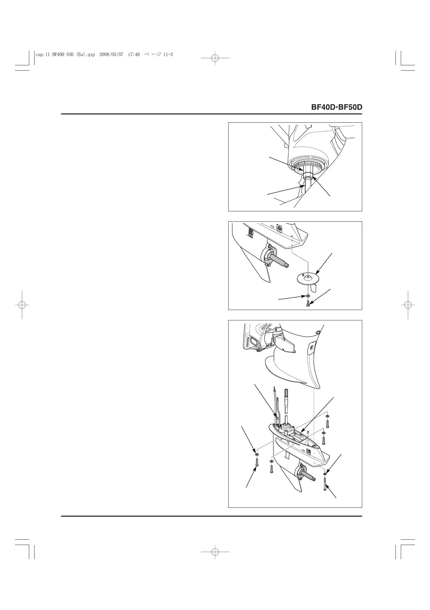
4) Loosen the shift rod B lock nut and disconnect the shift rod
A and the shift rod B by turning the shift rod joint nut.
5) Remove the 8 x 20 mm hex bolt and 8 mm washer, and
remove the trim tab from the gear case assembly.
6) Remove the four 10 x 40 mm hex bolts, four 10 mm
washers, 8 x 65 mm hex bolt and the 8 mm washer, and
remove the gear case assembly from the outboard motor
[Short/long shaft types only].
Remove the four 10 mm self-locking nut, four 10 mm
washers, 8 mm self-locking nut and the 8 mm washer, and
remove the gear case assembly and extension separator
from the outboard motor [Semi-long/extra-long shaft types
only] (P. 11-4).
Remove the two 6 x 10 mm dowel pins.
[2]
8 x 20 mm
HEX BOLT
[2]
LOCK NUT
[1]
SHIFT ROD
JOINT NUT
[3]
SHIFT ROD B
[1]
TRIM TAB
[3]
8 mm WASHER
[2]
GEAR CASE
ASSEMBLY
[5]
10 x 40 mm HEX
BOLT (4)
[4]
8 x 65 mm HEX BOLT
[3]
8 mm
WASHER
[6]
10 mm
WASHER (4)
[1]
6 x 10 mm
DOWEL PIN (2)
 Loading...