\
IGNITION SYSTEM
IGNITION SYSTEM INSPECTION
• If there
is
no spa
rk
at the plug, check all cennec- ,
--
-------:--:-
-
--------,
tions
for
loose
or
poor
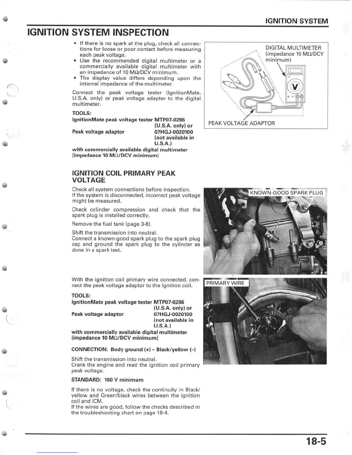
contact before measuring DIGITAL MULTIMETER
•
~~~h
~~a~:C~~~~nded
digital
multi
meter
or
a
,
.~.~_-,._---
.....
'\\
..
~
..
;.
~~;:,dua~
,
~
I
=
e
10
MOJDCV
commercially
available digital
multi
meter
with
.
an impedance
of
10
M!lIDCV
minimum.
•
The
display
value
differs
depending
upon
the :
'.
.
internal impedance
of
the
multi
meter.
<.
.
00
Connect
the
peak
voltage
tester
(lgnit
ionMate,
U.S.A. only)
or
peak voltage adap
ter
to
the digital
multi meter.
TOOLS:
IgnitionMate peak vottage
te
s
ter
MTP07-0286
(U.S.A.
only)
or
Peak
voltage
adaptor
07HGJ·0020100
(not
available
in
U.S
.A.)
with
commercially
available digital multi meter
(impedance
10
M
fl/
DCV
minimum)
IGNITION COIL PRIMARY PEAK
VOLTAGE
Check all
system
connec
t
ions
befo
re
inspection.
If
the
system
is
disconnected,
incorrect
peak
vol
tag
e
might
be
measured.
Check
cylinder
compression
and
check
that
the
spark
plug
is
ins
ta
lled
correctly
.
Remove
the
fu
el
tank
(page
3-8).
Shift
the
transmission
into
neutral.
Co
nn
ect
a
known'good
spark
plug
to
the
spark
plug
cap
and
ground
the
spark
plug
to
the
cyli
nder
as
done
in
a
spark
test.
PEAK VOLTAGE ADAPTOR
With
th
e
ign
i
tion
co
il
primary
wi
re
connected,
con-
re;;
~~~~~
i=====~
nect
the
peak
voltage
adaptor
to th
e
ignition
coil.
TOOLS:
IgnitionMate
peak
voltage
tester
MTP07
·0286
(U.S.A.
only)
or
Peak
voltage
adaptor
07HGJ-0020100
(not
available
in
U.S.A.)
w
ith
commerci
a
lly
available
digit
al
multi
meter
(impedance
10 M
fl/
DCV
minimum)
CONNECTION:
Body
ground
1+)
- Black/
yello
w H
Shi
ft
the
transmission
into
neut
ra l.
Crank
the
engine
and
read
the
ignition
coil
primary
peak
voltage.
STANDARD: 100 V
minimum
If
there
is
no
voltage,
check
the
continuity
in
Black!
yellow
and
Green/black
wires
between
the
ignition
coil
and
ICM.
If
the
wires
are
good,
follow
the
checks
described
in
the
troubleshooting
chart
on
page 18·4.
18-5
 Loading...