3-15
HRN216 MAINTENANCE
18. VALVE CLEARANCE
Valve clearance inspection and adjustment must be performed
with the engine cold.
CHECK
1. Disconnect the spark plug cap.
2. Remove the fan cover (P. 7 -3
).
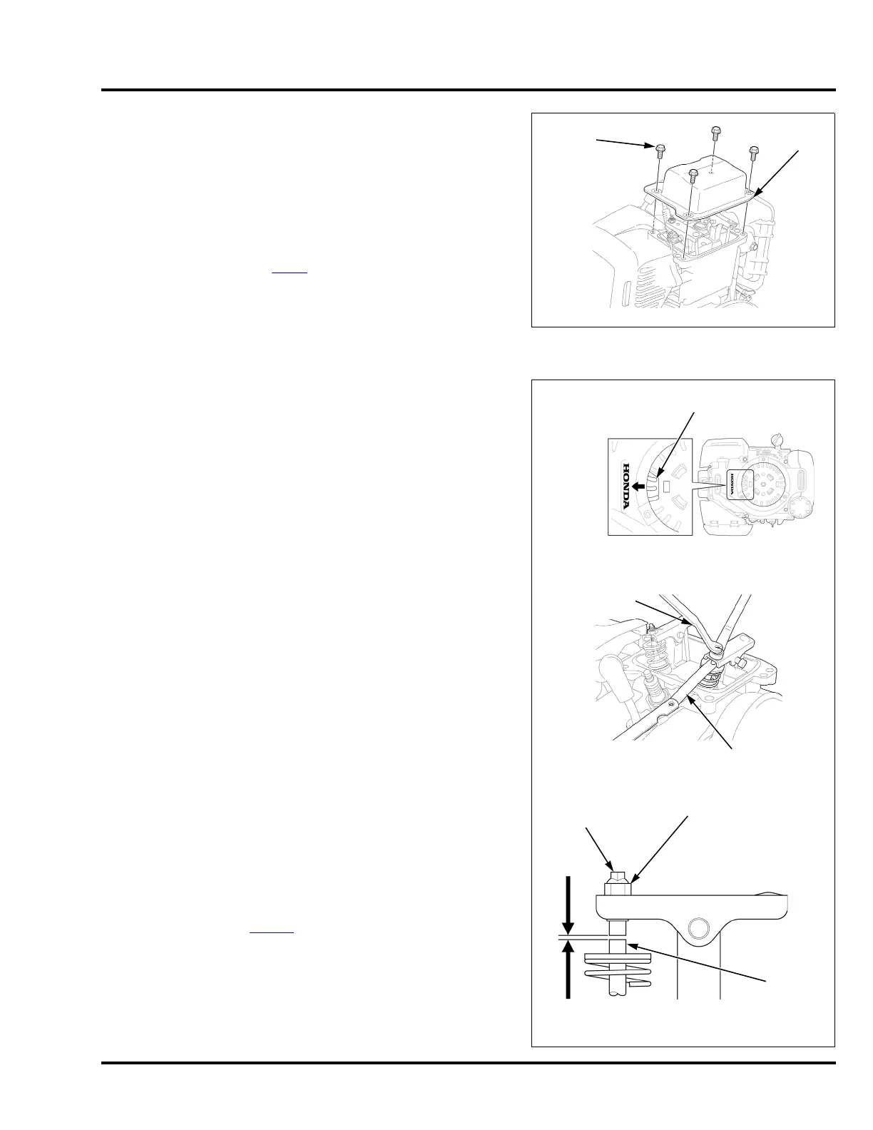
3. Remove the head cover bolts, and the head cover.
The cylinder head cover is made of very thin metal and
becomes bent or damaged during removal. If the head cover is removed, replace it with a new one to prevent oil
leaks.
4. Set the engine to top dead center (TDC) of the compression
stroke (both valves fully closed). Rotate the flywheel clockwise
until the magnet inside the flywheel faces the direction of the
cylinder head. This will position the engine at TDC of either the
compression or exhaust stroke. Rotate 360 degrees if
necessary. If it is hard to rotate the flywheel, remove the spark
plug.
5. Insert a feeler gauge between the valve adjusting screw and
valve stem to measure the valve clearance.
If adjustment is necessary, proceed as follows.
ADJUSTMENT
1. Hold the valve adjusting screw using the special tool and loosen
the valve adjusting screw lock nut.
2. Turn the adjusting screw to obtain the specified clearance.
3. Hold the valve adjusting screw and retighten the valve adjusting
lock nut to the specified torque.
4. Recheck the valve clearance, and if necessary, readjust the
clearance.
5. Apply Hondabond HT (or equivalent) to the cylinder head cover
installation surface (P. 1 0- 6
).
Installation is in the reverse order of removal.
VALVE CLEARANCE:
IN: 0.10 ± 0.02 mm
EX: 0.10 ± 0.02 mm
TOOL:
Valve adjusting wrench, 3 mm 07908-KE90200
TORQUE:
Valve adjusting lock nut: 8 N•m (5.9 ft-lb)
TORQUE:
Cylinder head cover bolt: 12 N•m (9 ft-lb)
HEAD
COVER
BOLT (4)
HEAD
COVER
FLYWHEEL
To increase valve clearance, screw out.
To decrease valve clearance, screw in.
FEELER
GAUGE
VALVE
ADJUSTING
SCREW
VALVE
STEM
VALVE
STEM
LOCK NUT
VALVE
ADJUSTING
WRENCH