5-5
HRN216 ENGINE REMOVAL/INSTALLATION
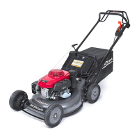
8. Disconnect battery charger connector on the handlebar
and then pull harness band clip out of the hole in the
handlebar.
Remove the harness from the harness guide by sliding it
through the opening in the loop.
9. Remove the recoil grip and rope from the handlebar
(P. 11-12
).
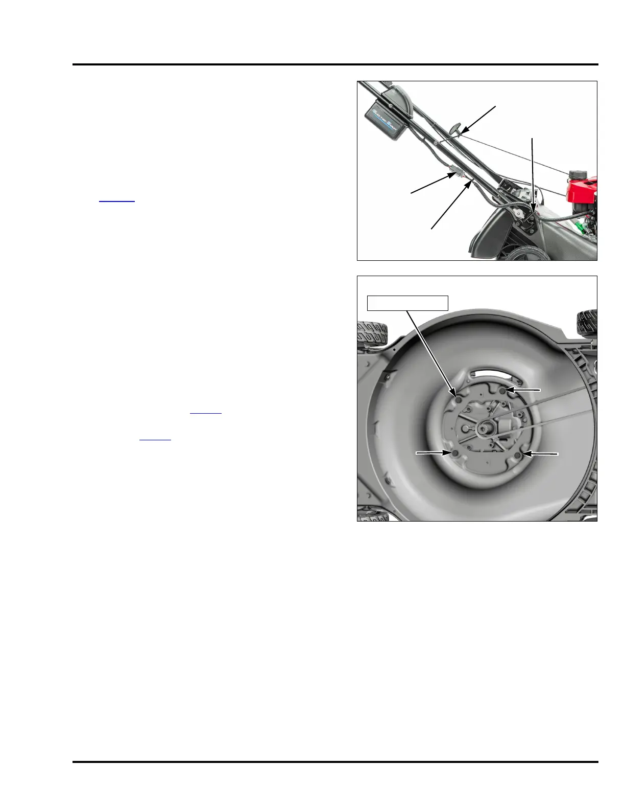
10. Support the engine, and remove the four 5/16-24 x 1
inch engine mounting bolts.
11. Remove the engine.
INSTALLATION
Installation is done in the reverse order of removal.
• Be sure to install the flywheel brake cable Z-fitting cable
end through the top side of the brake lever.
• Adjust the belt guide (P. 2-19
).
• Be sure the belt is properly routed through the shutter
assembly (P. 1 2- 4
).
• Be sure the blade holder Woodruff key is properly
installed, and properly tighten the blade holder bolt.
Failure to do so will result in blade holder bolt failure that
can cause the blade holder to come off.
Tighten the engine mounting bolts to the specified torque.
TORQUE: 21.6 N•m (15.9 ft-lb)
BATTERY
CHARGER
CONNECTOR
HARNESS
BAND CLIP
HARNESS
GUIDE LOOP
RECOIL
GRIP/ROPE
5/16-24 x 1 in BOLT (4)
21.6 N•m (15.9 ft-lb)

 Loading...