Commissioning
Instruction manual 854 ATG Page 13
3.2.3 Installation of displacer
• If a density displacer is used, note the engraved displacer weight
and displacer volume on a piece of paper for later use.
• Remove the test weight and attach the displacer to the wire
through a mounting hatch.
Note:
If there is no mounting hatch available, the displacer can be
installed by temporarily removing the gauge from the nozzle.
To provide electrical contact between the measuring wire and
displacer, thus permitting the discharge of static electricity and
preventing loss of the displacer, the displacer must be secured
to the measuring wire.
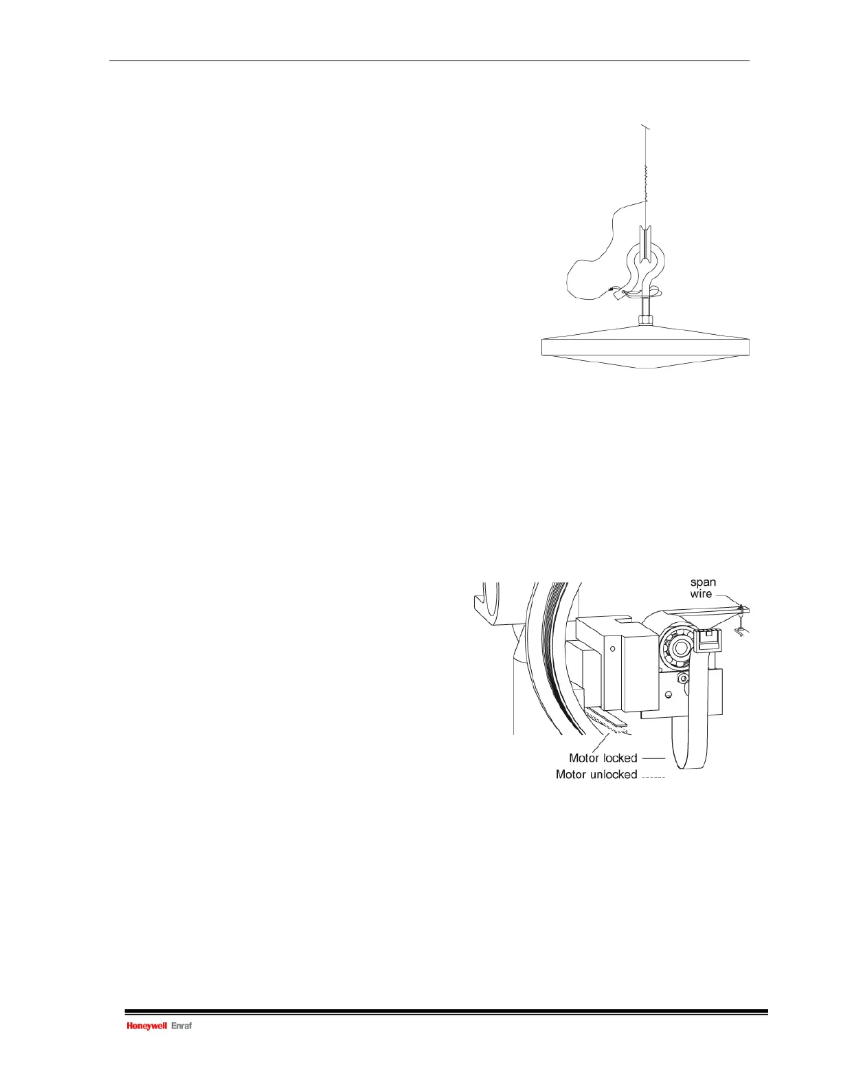
• Take an extra piece of wire and fasten one end to the measuring
wire, pass the other end through the hole in the end of the
displacer hook. Secure this end several times around the hook Figure 3.3 Mounting displacer
(see figure 3.3).
• Close the drum compartment cover.
3.2.4 Unlocking (locking) the motor block
T
he motor block is locked during transport to protect the force transducer.
After installing the measuring drum and displacer, the motor block locking device must be unlocked.
• Open the electronic compartment cover (front cover).
• Locate the transport bracket (see figure 3.4).
Loosen (do not remove) the Allen key screw and
turn the transport bracket the opposite way.
Use screwdriver for Allen key screws M4
(item 8 of the Honeywell Enraf tool set).
• Fix the Allen key screw of the transport bracket.
• Check the span wire. It should always be under tension
while both ends are correctly positioned in the levers of
the motor block and force transducer.
• Close the electronic compartment cover.
Figure 3.4 Motor block (un)locked
Note:
Use the same procedure for locking the motor block if the 854 ATG needs to be removed.

 Loading...


