Maintenance
Instruction manual 854 ATG Page 41
5.4 The electronic compartment
5.4.1 Detailed description
The electronic part of the 854 ATG requires no special maintenance.
However, a detailed description of the combination of the several parts is given in order to help you in case of
software-updates or system enhancements.
The control hardware is concentrated in the electronic compartment, which contains a minimum number of
sub-assemblies. The design of the 854 ATG is such that it makes replacement and service simple.
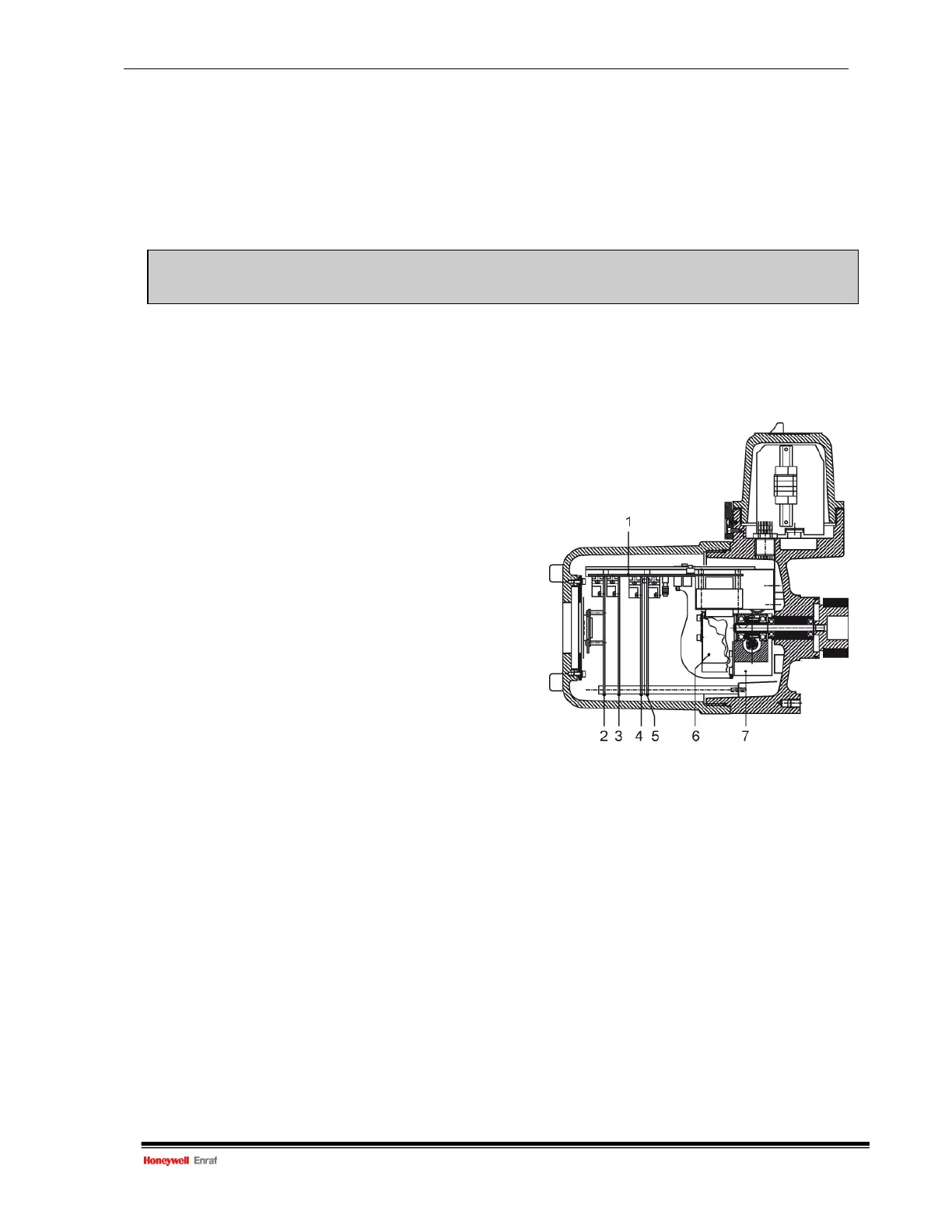
The electronic compartment contains the following sub-assemblies (refer to figure 5.4):
1 Back-plane
2 Printed circuit board XPU
(Xmission Processing Unit)
3 Printed circuit board SPU
(Servo Processing Unit)
4 Printed circuit board
(Optional board: HCU)
5 Printed circuit board GPS
(Gauge Power Supply)
6 Force transducer
7 Stepper motor frame including encoder disc
Figure 5.4 Cross section of the electronic
and terminal compartment
Caution
Never remove the electronic boards when the mains power is connected to the gauge.
It may damage the electronic circuits.

 Loading...


