Commissioning
Instruction manual 854 ATG Page 21
3.3.6 Ullage readout
When an ullage reading is required, the two items shown below
must be changed.
The ullage value is also transmitted to the host via the 2-wire
Honeywell Enraf field bus (or optional RS-channel).
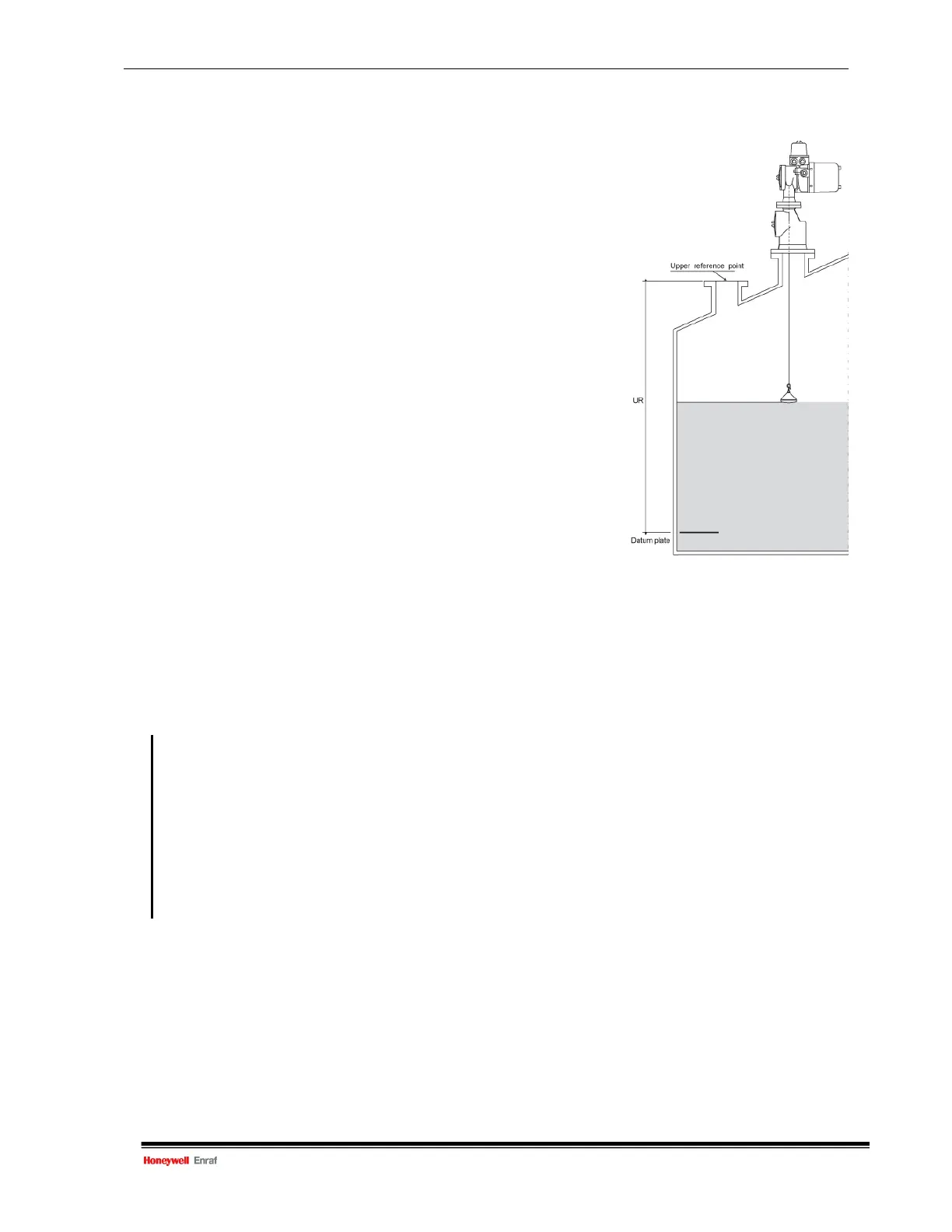
The ullage, or outage, measurement is referred to a ‘zero’ point at
the tank top (upper reference point).
The level, or innage, measurement is referred to a ‘zero’ point at
the tank bottom (datum plate).
Refer to figure
Note:
The high and low level alarms are “innage” alarms.
H
ence a high alarm condition occurs when there is
a low ullage value and visa verse.
Figure 3.8 Upper reference value
Item Name Description
W2= Protection level 2 Enter protection level 2 (default password: ENRAF2)
UR= Upper reference Format according to item LD.
The distance UR represents the distance from the ‘innage’ zero point
(datum plate) to the upper reference point at a dip hatch (or other point
at the tank top).
DE= Level type One character; either C, I or U.
C : for hydrostatic deformation compensated innage measurement
I : for innage measurement (default)
U : for ullage measurement
EX Exit Exit protection level.

 Loading...


