PNEUMATIC CONTROL FUNDAMENTALS
ENGINEERING MANUAL OF AUTOMATIC CONTROL
92
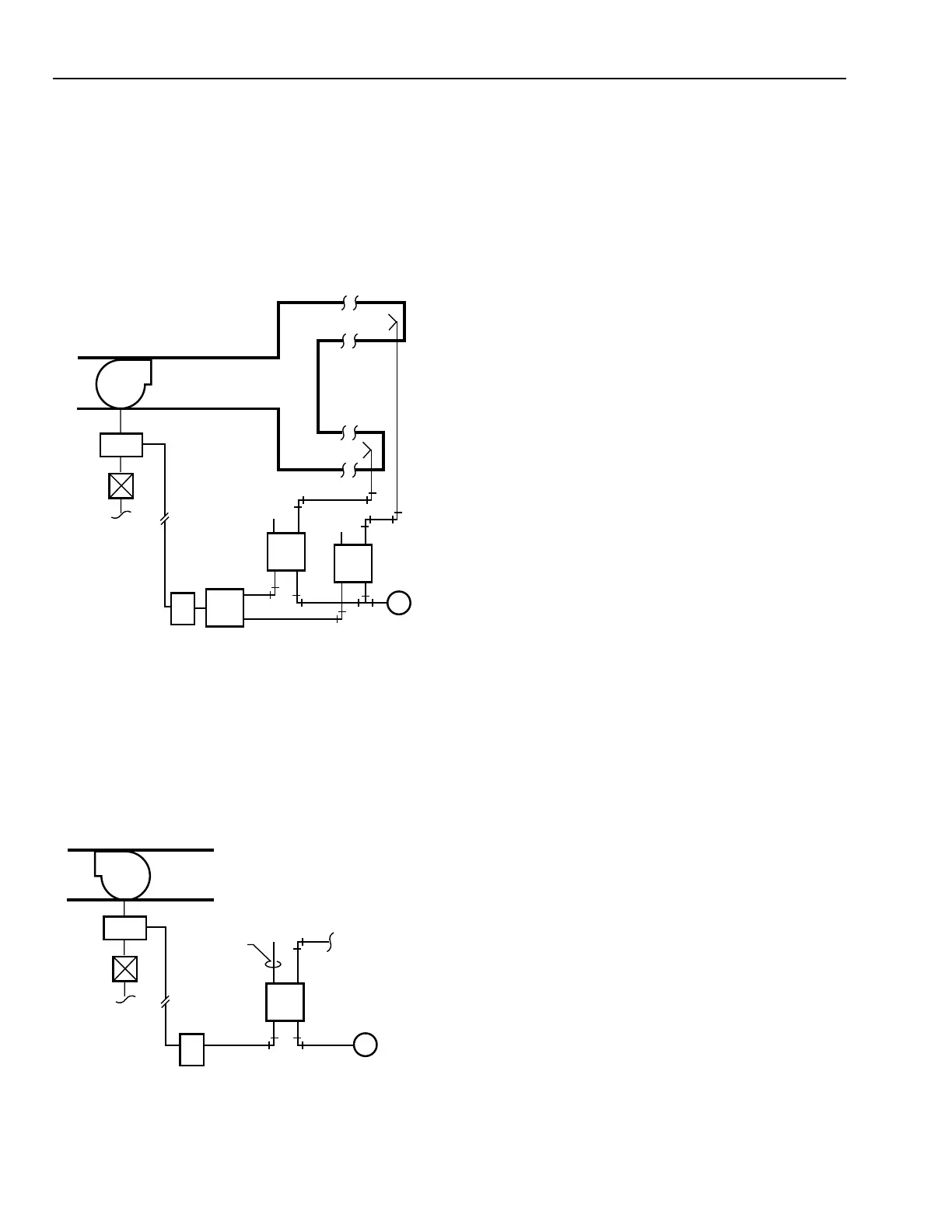
SUPPLY FAN CONTROL SEQUENCE
Any time the Supply Fan (Fig. 76) runs, the pressure
controller with the greatest demand, Static Pressure Controller
PC
1
or PC
2
, operates the Electronic-Pressure Transducer PT.
The controller used is determined by High Pressure Selector
Relay HSR. Transducer PT controls the Supply Fan Variable
Speed Drive (VSD) to maintain duct static pressure. The pick-
up probes for Static Pressure Controllers PC
1
and PC
2
are
located at the end of the east and west zone ducts.
VSD
L
B
RA
1.5 IN. WC
RA
1.5 IN. WC
PC
2
PC
1
M
2
EP
H
B
P
2
P
1
L
BM
H
PT
SUPPLY FAN
M10300
STARTER
EAST ZONE
WEST ZONE
HSR
VSD
REFERENCE PICK-UP
RUN TO 15 FEET
ABOVE ROOF
L
B
DA
0.05 IN. WC
PC
M
2
EP
H
1
PT
TO SPACE
STATIC PRESSURE
PICK-UP
RETURN FAN
M10299
STARTER
Fig. 76. Supply Fan Load Control.
RETURN FAN CONTROL SEQUENCE
Static Pressure Controller PC (Fig. 77) controls the return
fan variable speed drive to maintain space static pressure. The
pick-up probe is located in the space
NOTE: 1. Because of varying exhaust between occupied and
warm-up modes, space static pressure control of
the return fan is selected. Return fan tracking from
supply fan airflow is acceptable but is complex if
varying exhaust is worked into the control scheme.
2. Exercise care in selecting location of the inside
pick-up and in selection of the pressure controller.
Location of the reference pick-up above the roof
is recommended by ASHRAE.
3. To prevent unnecessary hunting by the return fan
at start-up, the supply fan control signal should be
slow loading such that the supply fan goes from
zero or a minimum to maximum load over three
minutes. Shut down should not be restricted.
WARM-UP/HEATING COIL CONTROL
SEQUENCE
Any time the Supply Fan (Fig. 78) runs and the return air
temperature is below 69F, Temperature Controller TC-1 trips
Snap-Acting Relay SA-1 to position Switching Relays SR-1
and SR-2 to initialize warm-up control. Relay SA-1 also
positions Switching Relay SR-4 to disable cooling controls.
Switching Relay SR-2 opens all interior VAV box dampers
and starts the hot water pump. Relay SR-1 switches the hot
water valve from normal control to warm-up control via
Controller TC-2 and modulates the hot water valve to maintain
a discharge air temperature setpoint of 90F.
NOTE: Fan powered perimeter VAV boxes are cool in this
mode and operate with the fans on and at the minimum
airflow (warm air) setpoints. Reheat valves at each
box operate as needed. This allows the warm-up cycle
to operate the air handling unit (AHU) fans at a
reduced and low cost power range.
Fig. 77. Return Fan Load Control.
 Loading...


