ENGINEERING MANUAL OF AUTOMATION CONTROL
BUILDING AIRFLOW SYSTEM CONTROL APPLICATIONS
277
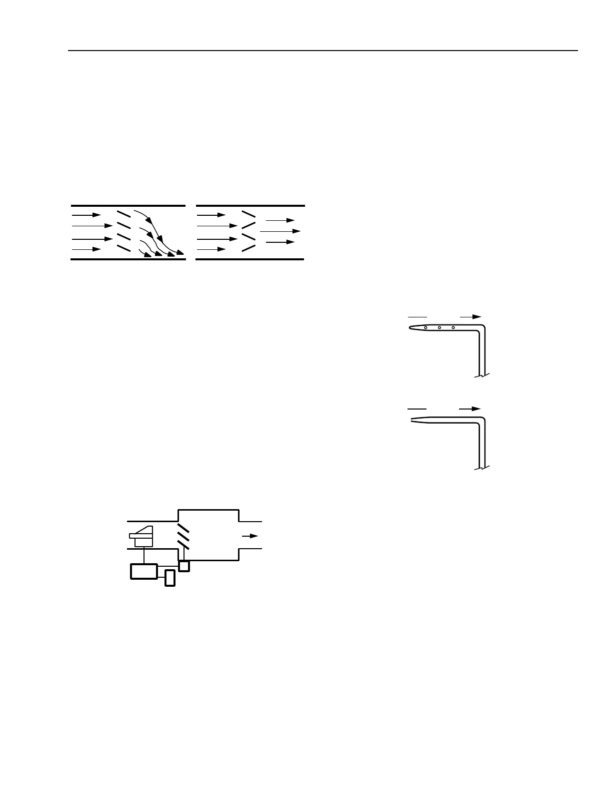
EFFECTS OF DAMPERS
Dampers are often used in ducts for mixing, for face and
bypass control of a coil, for volume control, or for numerous
other air volume controls. Figure 12 shows the velocity profile
in a straight duct section. Opposed blade dampers are
recommended where there are other system components
downstream of the damper such as coils or branch takeoffs as
they do not adversely distort the air velocity profile. Parallel
blade damper can be used where the airflow discharges into a
free space or a large plenum.
Fig. 12. Velocity Profile of Parallel Blade vs
Opposed Blade Damper.
EFFECTS OF AIR TERMINAL UNITS
A variety of air terminal units are available for air handling
systems. For VAV systems, the single duct, Variable Constant
Vo lume (VCV), throttling type air terminal unit (Fig. 13) is
typically used. With this device, the space thermostat resets the
setpoint of an airflow controller, varying the volume of
conditioned air to the space as required. Since a number of
these units are usually connected to the supply duct, it is the
collective requirements of these units that actually determines
the airflow in the main supply duct. In this type of system, the
supply fan is controlled to maintain a constant static pressure
at a point in the duct system so there is sufficient supply air for
all of the air terminal units.
MEASUREMENT OF AIRFLOW IN DUCTS
GENERAL
Total pressure and static pressure can be measured directly;
velocity pressure cannot. Velocity pressure is found by
subtracting the static pressure from the total pressure. This
subtraction is typically done by differential pressure measuring
devices.
PRESSURE SENSORS
Some applications require only the measurement of static
pressure. To obtain an accurate static pressure measurement, a
static pressure sensor (Fig. 14A) is used. This sensor has a
closed, bullet-shaped tip followed by small peripheral holes
that are perpendicular to the airflow for measuring air pressure.
The total pressure sensor (Fig. 14B) is similar except there is
an opening in the end of the tube and no openings along the
sides.
PARALLEL BLADE
DAMPER ILLUSTRATING
DIVERTED FLOW
OPPOSED BLADE
DAMPER ILLUSTRATING
NON - DIVERTED FLOW
C2652
AIR
TERMINAL
UNIT
AIRFLOW
CONTROLLER
ACTUATOR
THERMOSTAT
C2653
AIRFLOW
SENSOR
Fig. 14. Pressure Sensors.
Fig. 13. Single Duct, Variable Constant
Volume Air Terminal Unit.
AIRFLOW
AIRFLOW
C2654
A. STATIC PRESSURE SENSOR.
B. TOTAL PRESSURE SENSOR.
 Loading...


