ENGINEERING MANUAL OF AUTOMATIC CONTROL
CHILLER, BOILER, AND DISTRIBUTION SYSTEM CONTROL APPLICATIONS
374
CONTROL PRINCIPLES FOR STEAM
HEATING DEVICES
GENERAL
To control a steam supplied device, the system design should
include valves and other equipment required to produce the
amount of heat needed at design conditions. In addition, the
system should be capable of controlling a steady flow of heat
directly related to the demands of the thermostat or other
controller at load conditions from 0 to 100 percent.
To design a steam system that is capable of controlling the
various radiators and coils in a building, the pressure relationships
between the various elements of a steam heating system must be
analyzed under various load and system conditions.
MODULATING STEAM COIL PERFORMANCE
Figures 114 and 115 show a steam coil supplied from a 5
psig steam main, controlled by an oversized modulating valve
(Fig. 114) or a correctly sized modulating valve (Fig. 115), and
discharging condensate to the return through a trap. The figures
demonstrate the importance of proper sizing of the modulating
valve and the ability of the valve to control the output of the
coil. Refer to the Valve Selection and Sizing section for valve
sizing procedures.
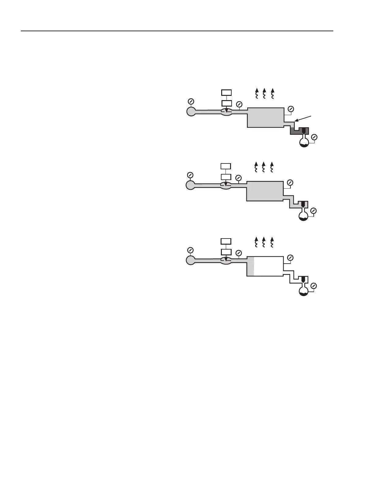
Oversized Valve
In Figure 114A a large valve is used to ensure 4 psi in the
coil. When the valve is full open, the coil is full of steam and
the output is 100,000 Btuh. The return header and trap are also
full of steam keeping the trap closed much of the time. The
trap opens slightly when water accumulates around the
thermostatic element allowing the condensate into the return
mains. The pressure drop through the valve and coil is small,
but large across the trap.
Figure 114B shows the pressure relationship and heat output
as the modulating valve closes to the half-open position. The
smaller opening in the valve requires 4 psi to get the steam
through the valve, called a 4 psi drop across the valve. This
leaves 1 psi in the steam coil header. Although the thermostat
has signaled to the valve to cut heat output in half, the coil is
still full of steam and the heat output is only reduced by 5
percent. The reduction is because of the difference in
temperature of 4 psi steam compared to 1 psi steam, assuming
50F air temperature entering the coil. The trap drop is 0.9 psi.
Most of the pressure drop between the supply and the return
mains is now across the steam valve. The portion of the
modulating valve stroke between half open and full open
reduces the heat output only 5 percent.
Figure 114C shows the quarter-open valve position. Half of
the coil surface is starved of steam, the heat output is reduced
to about half of the original value and the trap is full open. All
of the steam has been condensed in the coil before reaching the
trap. Virtually all of the drop between the supply and return
mains is dissipated through the control valve.
Fig. 114. Control Results with Oversized Valve.
The conclusions reached from Figure 114 are:
1. The sum of the individual pressure drops across the valve,
coil, and trap equals the pressure difference between the
supply and return mains.
2. Heat output changes little due to pressure change within
the coil, as long as the coil is full of steam.
3. Heat output changes little until the valve assumes most
of the pressure drop between supply and return mains.
4. Heat output from the coil is reduced by starving a part
of the coil surface of steam and allowing the surface to
cool off.
NOTE: Steam distributing coils allow reduced output without
the return end becoming cold.
THERMOSTAT
VALVE
STEAM
MAIN
RISER
MODULATING
VALVE
FULL OPEN
RETURN MAIN
AT ATMOSPHERIC
PRESSURE
RETURN
HEADER
3.9 PSI
4.0 PSI
COIL 0.1 PSI DROP
TRAP
3.9 PSI
0 PSI
5 PSI
HEAT OUTPUT
100,000 BTU/HR
DROP
THERMOSTAT
VALVE
STEAM
MAIN
RISER
MODULATING
VALVE
1/2 OPEN
RETURN MAIN
AT ATMOSPHERIC
PRESSURE
0.9 PSI
1.0 PSI
COIL 0.1 PSI DROP
TRAP
0.9 PSI
0 PSI
5 PSI
HEAT OUTPUT
95,000 BTU/HR
DROP
THERMOSTAT
VALVE
STEAM
MAIN
RISER
MODULATING
VALVE
1/4 OPEN
RETURN MAIN
AT ATMOSPHERIC
PRESSURE
0.02 PSI
0.02 PSI
COIL NO DROP
TRAP
0.02 PSI
0 PSI
5 PSI
HEAT OUTPUT
52,000 BTU/HR
DROP
A. FULL-OPEN VALVE.
B. HALF-OPEN VALVE.
C. QUARTER-OPEN VALVE.
4.98 PSI
DROP
4 PSI
DROP
1.0 PSI
DROP
M15077
 Loading...


