PNEUMATIC CONTROL FUNDAMENTALS
87
ENGINEERING MANUAL OF AUTOMATIC CONTROL
13
24
CAP
HIGH PRESSURE
GAGE
FROM
COMPRESSOR
FILTER
TWO-PRESSURE
REDUCING VALVE
EXH
MANUAL
SWITCH
MAIN PRESSURE
GAUGE
MAIN
AIR
C2375
CHANGEOVER CONTROL FOR TWO-
PRESSURE SUPPLY SYSTEM
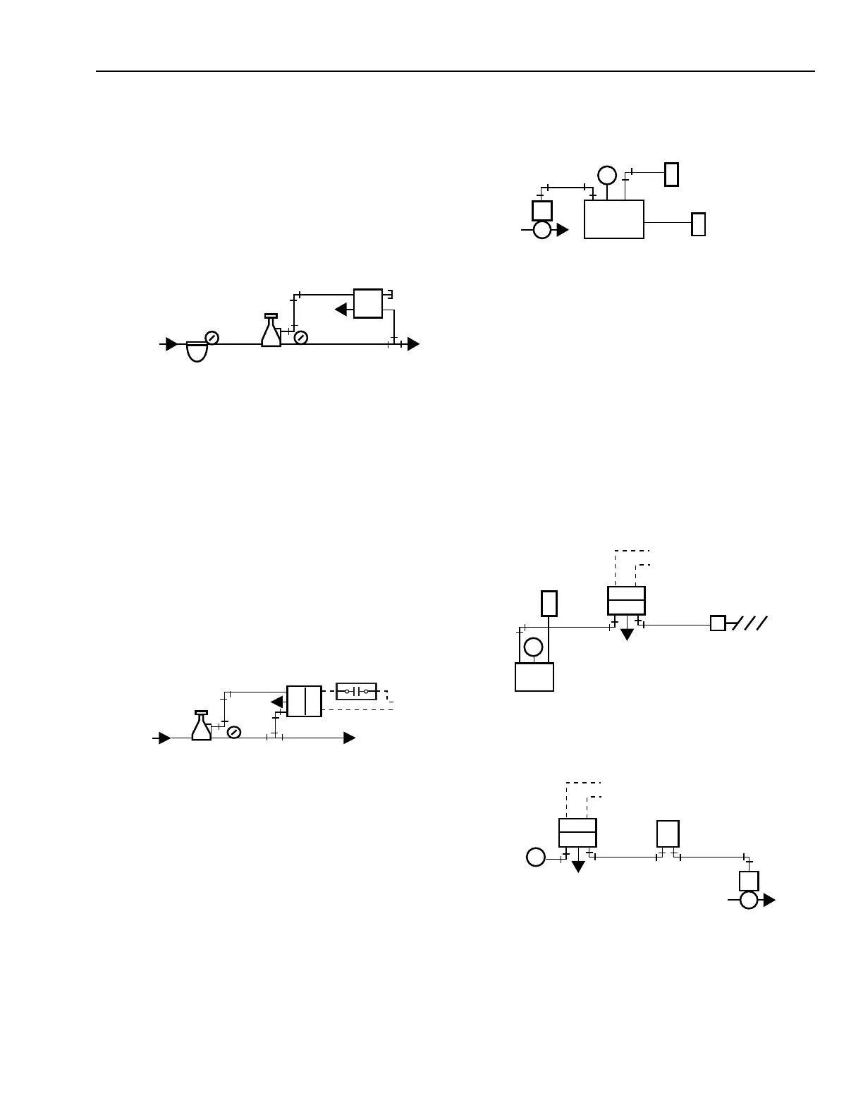
Figure 65 shows a manual switch used for changeover from
13 to 18 psi in the mains. Either heating/cooling or day/night
control systems can use this arrangement. In Position 1, the
switch supplies main pressure to the pilot chamber in the PRV.
The PRV then provides 18 psi (night or heating) main air
pressure to the control system.
FROM
COMPRESSOR
TWO-PRESSURE
REDUCING VALVE
X = NORMALLY DISCONNECTED
O = NORMALLY CONNECTED
EXH
MAIN
AIR
C2376
C
O
X
ELECTRIC
POWER
THERMOSTAT
OR
TIME CLOCK
E/P RELAY
GAUGE
Fig. 65. Two-Pressure Main Supply System
with Manual Changeover.
In Position 2, the manual switch exhausts the pilot chamber
in the PRV. The PRV then provides 13 psi (day or cooling) to
the system.
Figure 66 shows a two-pressure system with automatic
changeover commonly used in day/night control. A switch in
a seven-day time clock and an E/P relay provide the
changeover. When the E/P relay energizes (day cycle), the pilot
chamber in the PRV exhausts and controls at 13 psi. When the
electric-pneumatic relay de-energizes, the pilot chamber
receives full main pressure and the PRV provides 18 psi air.
according to a preset schedule. The system then provides the
scheduled water temperature to the convectors, fan-coil units,
or other heat exchangers in the system.
Fig. 67. Compensated Supply Water System
Using Dual-Input Controller.
ELECTRIC-PNEUMATIC RELAY CONTROL
Figure 68 shows one use of an E/P relay in a pneumatic
control circuit. The E/P relay connects to a fan circuit and
energizes when the fan is running and de-energizes when the
fan turns off, allowing the outdoor air damper to close
automatically when the fan turns off. The relay closes off the
controller branch line, exhausts the branch line going to the
damper actuator, and allows the damper to go to its normal
(closed) position. Figure 69 shows an E/P relay application
that shuts down an entire control system.
Fig. 66. Two-Pressure Main Supply System with
Automatic Changeover.
COMPENSATED CONTROL SYSTEM
In a typical compensated control system (Fig. 67), a dual-
input controller increases or decreases the temperature of the
supply water as the outdoor temperature varies. In this
application, the dual-input controller resets the water
temperature setpoint as a function of the outdoor temperature
EXH
M
XOC
MIXED AIR
SENSOR
BMS
FAN
VOLTAGE
E/P
RELAY
N.C. DAMPER
ACTUATOR
N.C. DAMPER
C2361
DA CONTROLLER
C2358
EXH
N.C.
VALVE
THERMOSTAT
M
B
M
XO
C
SYSTEM
INTERLOCK
VOLTAGE
E/P RELAY
Fig. 68. Simple E/P Relay Combination.
Fig. 69. E/P Relay Combination for System Shutdown.
M
VALVE
HOT WATER SUPPLY
TEMPERATURE
SENSOR
OUTDOOR AIR
TEMPERATURE
SENSOR
CONTROLLER
B M S
1
S
2
C2356
 Loading...


