ENGINEERING MANUAL OF AUTOMATIC CONTROL
CHILLER, BOILER, AND DISTRIBUTION SYSTEM CONTROL APPLICATIONS
375
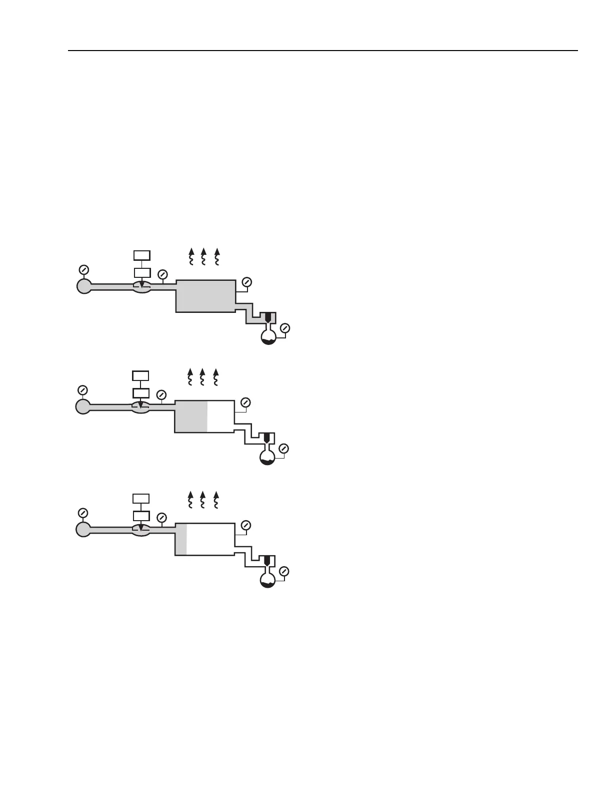
Correctly Sized Valve
The valve in Figure 115A is sized for a 4 psi pressure drop
when it is full open leaving 1 psi of steam for the coil and the
trap. Full heat output of the coil is 95,000 Btuh and most of the
drop between supply and return mains occurs across the valve.
Figure 115B shows the valve in the half-open position. The
output of the coil is cut approximately in half (54,000 Btuh).
This is in contrast to the oversized valve application (Fig. 100B)
where the heat was cut only 5 percent.
Figure 115C shows the output cut to 27,000 Btuh with the
valve in the quarter-open position. In contrast, the oversized
valve in the quarter-open position produced 52,000 Btuh.
SUPPLY AND RETURN MAIN PRESSURES
The supply main pressure should be constant and sufficient
to allow an 80 percent drop through the control valve and still
leave enough steam pressure downstream from the valve to
produce the desired heat output. If boiler pressure is not
constant, install a pressure reducing valve ahead of all steam
supplied devices where output temperatures may vary rapidly
with steam pressure fluctuations.
Even though the control valves do not change position,
variations in return main pressure causes fluctuations in steam
flow through control valves. From a control standpoint, an
atmospheric return with a condensate pump is more effective
than a vacuum return with a vacuum pump that can cycle over
a range of several inches of vacuum.
As an example of the effect of fluctuating supply and return
main pressures, assume a system where the boiler cycles so
that it shuts off at 6 psi and cuts in at 2 psi. On the same system
assume that a vacuum pump is used which cuts in at 4 in. Hg
and shuts off at 8 in. Hg of vacuum. The pressure difference
between supply and return mains can vary from a minimum of
4 psi to a maximum of 10 psi as the boiler and vacuum pump
cycle. This means a 60 percent variation in capacity of the
control valves in the building as the pressure fluctuates. Control
valves correctly sized for 4 psi are 60 percent too large during
periods when a 10 psi difference exists across the supply and
return mains.
SYSTEM DESIGN CONSIDERATIONS FOR
STEAM COILS
Figure 116 shows the optimum design conditions and piping
arrangement for a steam supplied heating coil. Considerations
for effective control are:
1. Steam mains held close to design pressures. Refer to
SUPPLY AND RETURN MAIN PRESSURES.
2. Returns at atmospheric pressure, unless lifts (condensate
pumps) are required in the returns.
3. Traps sized to pass design condensate flow at 1 psi drop.
4. An equalizer line to prevent formation of a vacuum
within coil.
5. A control valve pressure drop of 80 percent of the
difference between supply and return main pressures.
Fig. 115. Control Results with Correctly Sized Valve.
The conclusions reached from Figure 115 are:
1. A valve with a large pressure drop will be effective in
controlling heat output over its entire stroke.
2. The valve, not the trap, takes up most of the pressure
drop between supply and return mains.
THERMOSTAT
VALVE
STEAM
MAIN
RISER
MODULATING
VALVE
FULL OPEN
RETURN MAIN
AT ATMOSPHERIC
PRESSURE
0.9 PSI
1 PSI
COIL 0.1 PSI DROP
TRAP
0.9 PSI
0 PSI
5 PSI
HEAT OUTPUT
95,000 BTU/HR
DROP
THERMOSTAT
VALVE
STEAM
MAIN
RISER
MODULATING
VALVE
1/2 OPEN
RETURN MAIN
AT ATMOSPHERIC
PRESSURE
0.02 PSI
0.02 PSI
COIL NO DROP
TRAP
0.02 PSI
0 PSI
5 PSI
HEAT OUTPUT
54,000 BTU/HR
DROP
THERMOSTAT
VALVE
STEAM
MAIN
RISER
MODULATING
VALVE
1/4 OPEN
RETURN MAIN
AT ATMOSPHERIC
PRESSURE
0.01 PSI
0.01 PSI
COIL NO DROP
TRAP
0.01 PSI
0 PSI
5 PSI
HEAT OUTPUT
27,000 BTU/HR
DROP
A. FULL-OPEN VALVE.
B. HALF-OPEN VALVE.
C. QUARTER-OPEN VALVE.
C2929
4.98 PSI
DROP
4.99 PSI
DROP
4 PSI
DROP
 Loading...


