ENGINEERING MANUAL OF AUTOMATIC CONTROL
DAMPER SELECTION AND SIZING
466
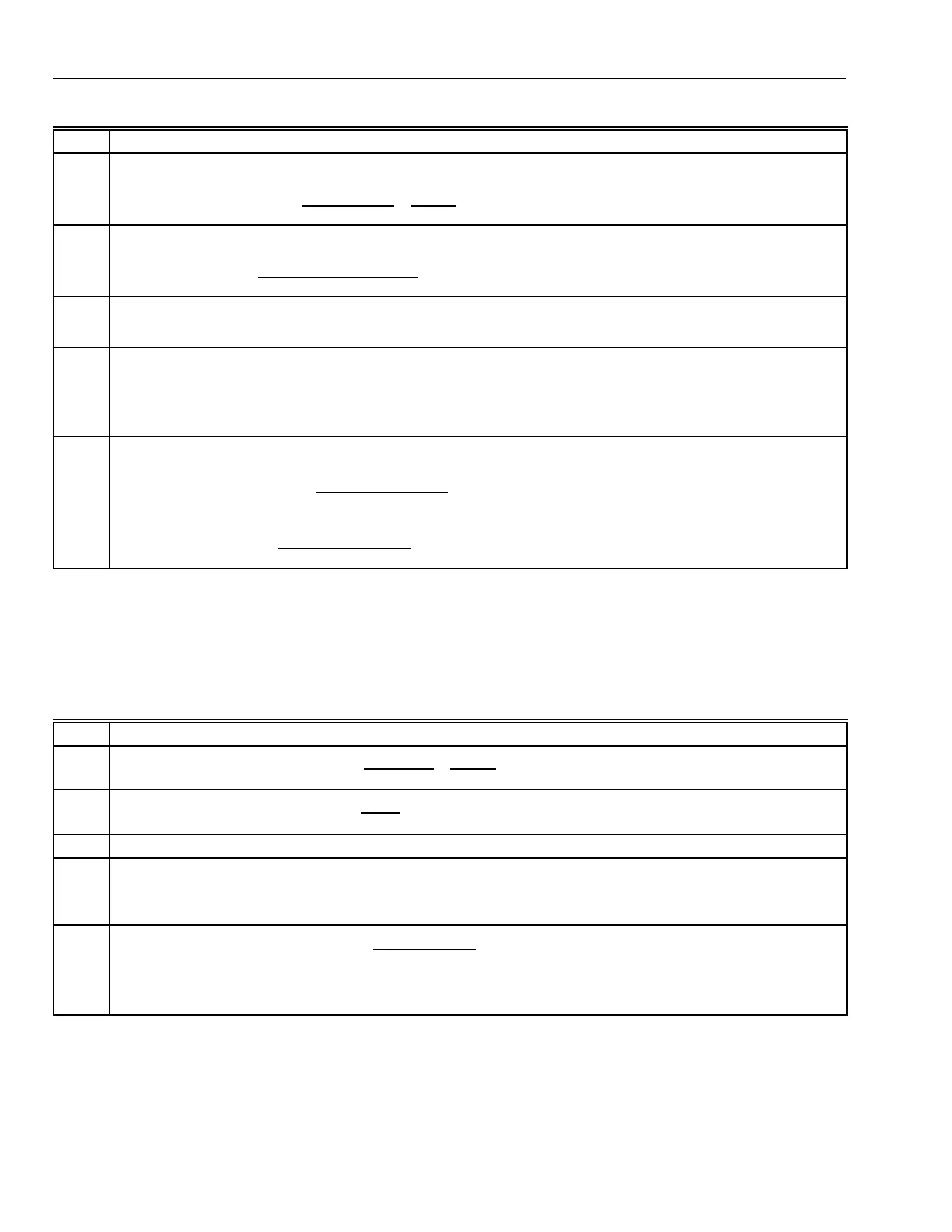
Table 4. Damper Sizing Procedure.
Table 5. Damper Sizing Example.
Step Procedure
1
Calculate the approach velocity:
Approach velocity (fpm) =
Airflow (cfm)
Duct Area (in
2
)
x
144 in
2
1 ft
2
2
Using the approach velocity from Step 1, calculate a correction factor:
Correction factor =
10
6
[Approach velocity (fpm)]
2
3
Calculate the pressure drop at 1000 fpm:
Pressure drop at 1000 fpm = Pressure drop at approach velocity x correction factor (Step 2)
4
Calculate free area ratio
a
:
For pressure drops (Step 3) ≥ 0.23:
Ratio = [1 + (21.3265 x pressure drop)]
–0.3903
For pressure drops (Step 3) < 0.23:
Ratio = [1 + (79.7448 x pressure drop)]
–0.2340
5
Calculate damper area (in
2
):
For parallel blade dampers:
Damper area (in
2
) =
()
Duct area (in
2
) x ratio
0.37
0.9085
For opposed blade dampers:
Damper area (in
2
) =
()
Duct area (in
2
) x ratio
0.3810
0.9217
a
T
he free area of a damper is the open portion of the damper through which air flows. The free area ratio is the open area
in a damper divided by the total duct area.
Step Example
1
Approach velocity (fpm) =
20,000 cfm
2304 in
2
x
144 in
2
1 ft
2
= 1250 fpm
2
Correction factor =
10
6
1250
2
= 0.64
3 Pressure drop at 1000 fpm = 0.6 in. wc x 0.64 = 0.038 in. wc
4
Free area ratio = [1 + (79.7448 x 0.038)]
–0.2340
= 4.03
–0.2340
= 0.722
5
Damper area (parallel blades) =
()
2304 in
2
x 0.722
0.37
0.9085
= 4496
0.9085
= 2083 in
2
 Loading...


