BENDIX/KING RDR 2000
Rev 7, July/2002 00643I05.TDC Page 3-3
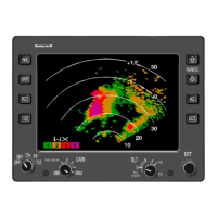
TABLE 3-1 IN 182A CONTROL FUNCTIONS
(reference Figures 3-1 & 3-2)
CONTROL/DISPLAY FUNCTION
BRT control Adjusts brightness of the display for varying cockpit light conditions.
Wx pushbutton Selects the weather mode (Wx) when pressed. Wx appears in display.
WxA pushbutton
Selects weather alert mode (WxA) when pressed. Magenta area flashes. WxA appears
in the display.
Wx/WxA pushbutton Toggles between Weather and Weather Alert mode in units with Vertical Profile option.
VP pushbutton
Selects and deselects the Vertical Profile mode of operation on units containing this op-
tion.
MAP pushbutton
Selects ground mapping mode (MAP) when pressed. MAP appears in the display. Red
color is not used in the MAP mode.
NAV pushbutton
Selects Navigation mode and displays preprogrammed waypoints when system is used
with optional radar graphics unit and Flight Management System.
TILT control
Turn the knob to adjust antenna tilt. Adjusts the antenna to move the radar beam up to
a maximum of +15
°
above the horizontal, or to a maximum of -15
°
below the horizontal
position. The horizontal position is indicated as 0
°
on the control. The tilt angle is dis-
played in the upper right corner of the indicator. Pulling this knob out disables stabiliza-
tion. If the system is in a non-stabilized installation, "STAB OFF" will appear in the upper
left corner of the screen.
RANGE increase
Clears the display and advances the pushbuttonindicator to the next higher range each
time the pushbutton is pressed (eg: 20 to 40, 40 to 80, etc.), until 240 mile range is
reached. The range selected is displayed in the upper right corner on the last range
mark, and the distance to each of the other range mark circles is displayed along the right
edge of the circles (arcs).
RANGE decrease
Clears the display and places the indicator pushbutton in the next lower range each time
the pushbutton is pressed (eg: 40 to 20), until the minimum range of 10 mile is reached
at the outermost range mark or ring.
TRACK left
Moves azimuth line to the left in 1
°
steps pushbuttonuntil 45
°
is displayed when button is
pushed. Also, used to select the vertical "slice" to be displayed when in Vertical Profile
mode on units with this option and increments in 2
°
steps after each horizontal scan.
TRACK right
Moves azimuth line to the right in 1
°
steps pushbuttonuntil 45
°
is displayed when button
is pushed. Also, used to select the vertical "slice" to be displayed when in Vertical Profile
mode on units with this option and increments in 2
°
steps after each horizontal scan.
GAIN control
Varies the radar receiver gain when in the MAP mode. Gain and STC are preset in the
Wx, WxA and VP modes.
ROLL TRIM
Adjust for a mechanical error of 2
°
or less if the radar sensor is not mounted parallel to
the wings. If the error is greater than 2
°
, the radar sensor must be removed and mechan-
ically aligned as close to 0
°
as possible.
 Loading...