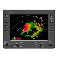
BENDIX/KING RDR 2000
Page 3-4 00643I05.TDC Rev 7, July/2002
TABLE 3-2 IN 182A FUNCTION SELECTOR SWITCH POSITIONS
(reference Figures 3-1 & 3-2)
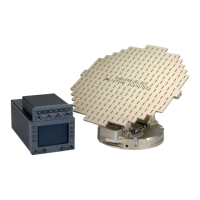
3.2.2 ART 2000 FAULT CODES
TABLE 3-3 ART 2000 FAULT CODES
POSITION FUNCTION
OFF OFF position removes primary power from the system.
SBY (standby)
SBY position places system in the standby condition during warm-up period and when
the system is not in use. The screen is blank with word STBY displayed in the lower left
corner. NAV mode may be selected while in standby. No transmission exists in the SBY
condition.
TST (test)
TST position selects test function to determine operability of the system. A test pattern
is displayed and the 80 mile range is automatically selected, but can be changed. No
transmission exists in the TST condition.
ON
ON position selects the condition for normal operation. Radar transmission exists in the
ON position. The Wx mode and 80 mile range are automatically selected when turned
on.
LOG
LOG position is used only when a Bendix/King IU 2023 series radar graphics unit is in-
stalled with a compatible long range navigation system. This mode lists the latitudes and
longitudes of selected waypoints, selected VOR frequencies and bearings and distances
to waypoints. No radar transmission occurs in this mode.
Error Code Description
IN FLT 6:
Indicator is transmitting 429 control word. No 453 Radar word.
STB LMT:
Unit has exceeded 30° combined pitch and roll deflection.
TX FLT/ANT FLT:
These faults, when alternately displayed in the fault field, indicate
that the RT unit (ART 2000) is unable to communicate with the
configuration module (CM 2000)
ANT FLT:
Indicates a problem with either the drive or sensor systems on the
antenna drive system.
TX FLT:
Indicates a problem on the TX or RX circuits of the ART 2000.(TX
FLT is always present when the ART 2000 is in the test mode.)
WX FLT:
Indicates that the information transmitted to the indicator, on the
453 bus, does not reflect the 429 control sent by the indicator to
the RT. This will be apparant in a three indicator system if the
third indicator controls are not set identical to No.1 or No.2 indi-
cator.
429 FLT:
This indicates the 429 control bus is not fuctioning correctly.
STAB OFF:
Indicates that the 400 Hz. reference is missing or incorrect for the
configuration programmed. Indicates that the tilt knob may be in
the stab off position (Outer position).
 Loading...