19
Mounting and Connection Instructions IB2 16 I/O Expander
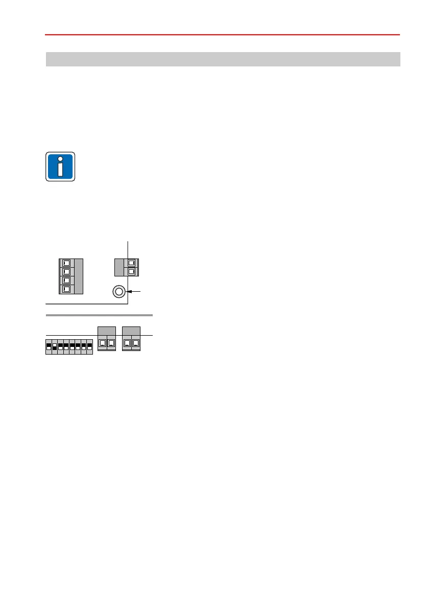
• Mount the circuit board on the housing base using the
supplied fixing materials (Lemosa spacing pieces).
• Screw the corner of the circuit board marked with PE on the
grounded housing base using a metal screw.
• Bridge connections "Wall" and "Tamper".
(The tear-off protection and the tamper switch are connected
to the control panel PCB.)
4.2 Mounting in the panel housing
Mounting on the metal housing base of the control panel or in a separate metal housing.
The circuit board size corresponds with the existing I-BUS modules.
Please refer to Chapter “Grounding and Shielding” in the Instructions for the Installer of the MB-
Secure control panel.
4. Mounting
4.1 Guidelines
In a housing, which is designed for subsequently installation of a lock, a VdS certified
lock insert (e.g. 028051) has to be installed instead of a plastic cover for systems
according to VdS and EN.
For systems, in which the panel is not conform to the EN guidelines, the EN-markings
have to be removed from the panel.
PE
ON
1 2 3 4 5 76 8
Wall Tamper
 Loading...


