21
Mounting and Connection Instructions IB2 16 I/O Expander
5. Installation guidelines
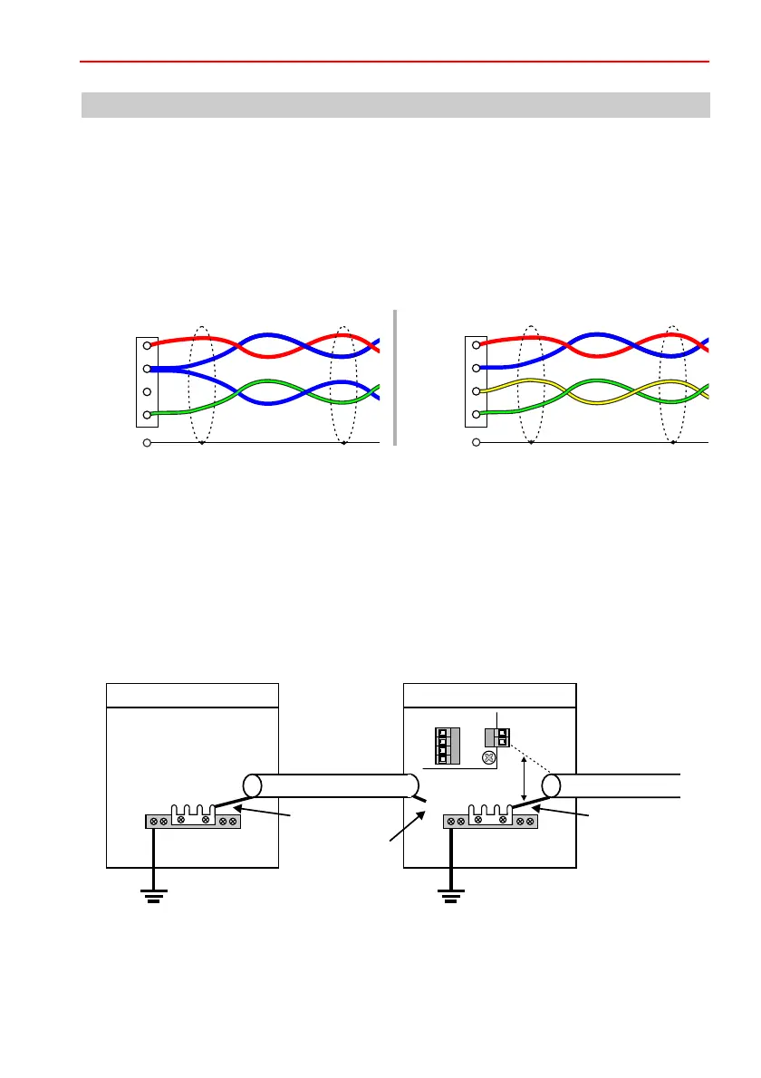
5.1 BUS connecting cable
The BUS connecting cable must be a shielded, twisted pair line. Wires must correspond with the
diagram below.
The corresponding line cross-sections can be found in the Installation Instructions of the intruder
alarm control panel (See chapter “Lines”).
Connect the shield in the housing to the shield connection bar. Keep the shield connections as short
as possible to avoid the risk of a short circuit.
5.2 Grounding and shielding when installing in a separate housing
When installing the module in a separate housing,
(see above).
The shielding is connected on one side to the shield terminal bar in the panel.
• The shielding of the incoming BUS cable is not connected.
• The shielding of the outgoing BUS cable is connected to the shield terminal bar of the housing or
the shield connection of the PCB.
• The shield terminal bar in each housing must be connected to a separate PE.
the devices are daisy chained via a shielded
twisted pair cable
Shield
Shield
IB2BUS-2
+12 V DC
A / Data
0 V
B
+12 V DC
A
0 V
B
PE PE
PE
X
Panel
16 I/O module
connected connected
not connected
to the next
BUS user
shield
terminal bar
BUS connecting
cable
shield
terminal bar
Shield
connection
or
 Loading...


