22
Mounting and Connection Instructions IB2 16 I/O Expander
6. Programming
6.2 Bus End-of-line resistor(EOL)
Changes to the DIP switch positions are only accepted after a reset. With the exception
of the DIP switch S8 which is immediately accepted when in operation.
6.2.1 EOL on IB2 interface
With jumpers JP1 and JP2 the EOLresistor of the interface is activated/deactivated.
Basically note: The bus line must be terminated at .
IB2
both ends with 120 Ohm
Principle: EOL resistor on IB2 BUS interface:
On BUS-2 interface the EOL resistors must be deactivated.
Remove jumpers if required (JP1 and JP2).
6.2.2 EOL on BUS-2 interface
- The user is at the of the line:
- EOLresistor
- The user is of the line:
- EOL resistor
beginning or end
Activate
between the beginning or end
Deactivate
Procedure:
Activate EOL resistor: Set jumpersboth
Deactivate EOL resistor: Remove jumpersboth
JP2
JP1
JP2
JP1
JP2
JP1
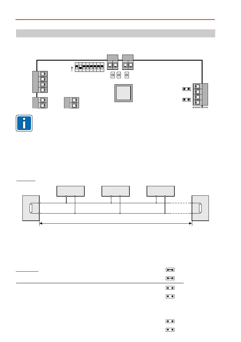
6.1 Position of jumpers and DIP switch
ON
1 2 3 4 5 76 8
LED 1 2 3
JP1
DIP switch
CPU
1 9
0V
A/D
0V
0V
U-EXT
U-EXT
UB
B
1
2
3
4
ON
JP2
2 10
user 2 user 3 user 4first user last user
max. 1000 m
A
B
R120
R120
 Loading...


