25
Mounting and Connection Instructions IB2 16 I/O Expander
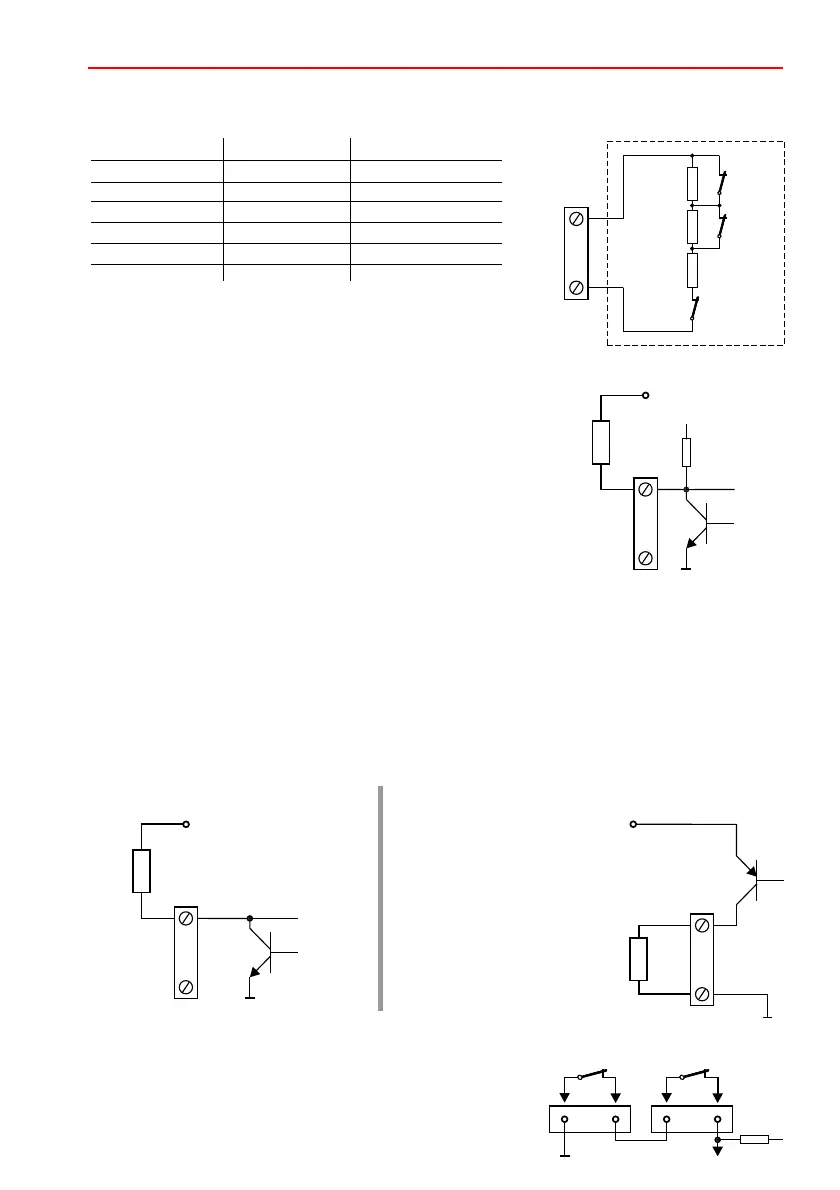
8.3 Outputs
The outputs from U_EXT = 5 – 15 V DC are short circuit resistant and current limited to 50 mA.
The maximum permissible current via this output for U_EXT> 15 V DC to 30 V DC is calculated as
follows:
I_max = 60 mA - 2 x (U_EXT - 15 V)
The functions "Low-aktive" or "High-aktive" can be assigned to the outputs via the programming.
8.4 Tamper connection
If the connection for the tear-off protection (wall) or the
connection for the tamper switch (tamper) is not required,
the contacts must be bridged.
The outputs are short-circuit resistant and current limited to 50 mA.
The load on these outputs can be powered at 9 – 15 V DC.
8.2.3 Input programmed as output
Status Nominal value Range
- Short circuit 800
- good 1 k 800 to 1.5 k
- Alarm 2 k 1.5 k to 3.2 k
- Fault 4 k 3.2 k to 4.5 k
- Alarm + Fault 5 k 4.5 k to 17.5 k
- Tamper/Break 17.5 k
The values are fixed.
£
³
W
W W W
W W W
W W W
W W W
W
8.2.2 Input with double balanced evaluation
Detector, e.g.
Motion detector
Fault
Alarm
Tamper
IN1 – 16
0 V
R_F
3k
R_A
R_T
1k
1k
IN1 – 16
0 V
UB (9 - 15 V DC)
RL
With this wiring, the connection
U_ext must be wired on the
circuit board. If the voltage
value falls below U_ext < 3 V, a
fault is transmitted to the
control panel.
"Active-high" output wired:"Active-low" output wired:
0 V
U = 5 V – 30 V DC
RL
OUT 1 - 16
(low)
OUT 1 - 16
(high)
0 V
U_EXT = 5 – 30 V DC
RL
WALL TAMPER
 Loading...


