20
Mounting and Connection Instructions IB2 16 I/O Expander
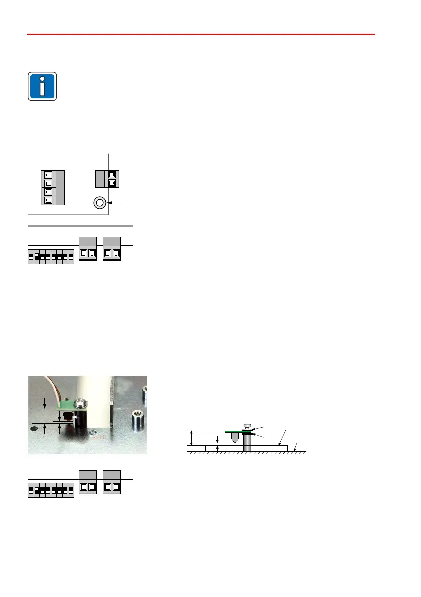
4.3.2 Install Tear-off protection
Screw the PCB with the tear-off contact on the spacer to the mounting surface as shown below. The
length of the spacer depends on the used housing (see P02916-47-002-xx).
Distance between the switch and the bottom plate approx. 2 mm or approx. 15 mm between the PCP
top and the bottom plate. Place washer(s) underneath to adjust positioning if necessary.2
1
2
3
4
Washer above
Washer(s) below for height adjustment
Bottom plate
Mounting surface
2 mm
3
42
1
15 mm
2 mm
15 mm
Tear-off contact
Connect the tear-off contact to the "Wall" connection.
The complete tear-off protection incl. spacers in various lengths is available as accessory,
Item no. 055140, PU = 5 piece.
4.3.1 Install 16 I/O module in the housing
4.3 Mounting in a separate housing
As per EN, only a MB-Secure housing is permitted.
cable length max. 1000 m
When installing the 16 I/O module in a separate housing, use a suitable housing from
our catalog.
(ZG20, ZG2, ZG3.1 or ZG4).
Permitted between control panel and 16 I/O module: .
• Mount the circuit board on the housing base using the
supplied fixing materials (Lemosa spacing pieces).
• Screw the corner of the circuit board marked with PE on the
grounded housing base using a metal screw.
(Grounding and shielding is in accordance with Chapter 5.2.)
• Connect the door contact of the housing to the "Tamper"
connection.
PE
ON
1 2 3 4 5 76 8
Wall Tamper
ON
1 2 3 4 5 76 8
Wall Tamper
 Loading...


