Lynx Plus Series Installation and Setup Guide
- 7 -
Wiring Connections
Wiring Overview
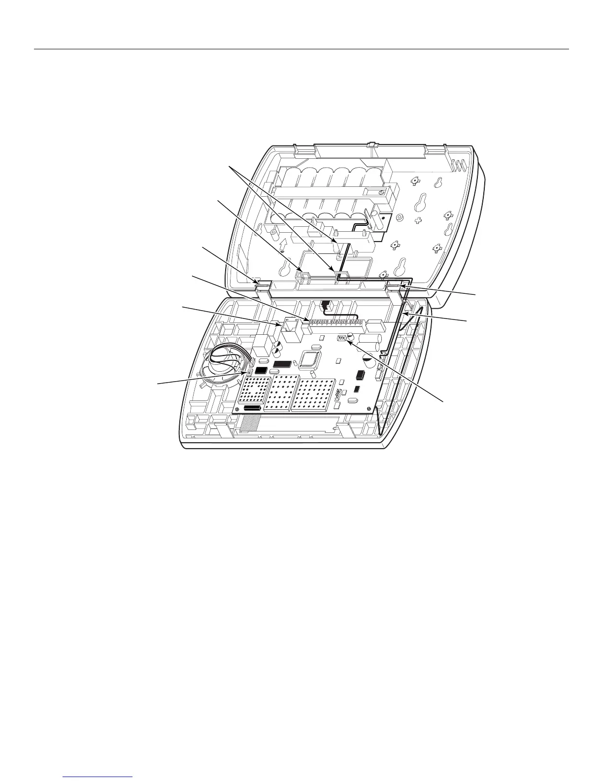
The following summarizes the connections required. Refer to the Wiring Connections paragraph and the
Summary of Connections diagram on the inside back cover when making connections. Ensure that the
battery cable is routed as shown in the figure below.
1000-300-006-V2
LOCAL
SOUNDER
DISABLE
SWITCH
MOUNTING
HOOK
TIE-WRAP
POINT
TELEPHONE
CONNECTION
TERMINAL
STRIP
BATTERY
CABLE
MOUNTING
HOOK
WIRE
ROUTING
TUNNELS
POWERLINE CARRIER
DEVICE CONNECTOR
Wiring Connections
1. Make Earth Ground Connection - The designated earth ground terminal (1) must be terminated in a good earth ground
for the lightning transient protective devices in this product to be effective. The following are examples of good earth
grounds available at most installations:
Metal Cold Water Pipe - Secure a non-corrosive metal strap (copper is recommended) to the pipe that is electrically
connected and secured to which the ground lead is electrically connected and secured.
AC Power Outlet Ground - Available from 3-prong, 120VAC power outlets only. To test the integrity of the ground
terminal, use a three-wire circuit tester with neon lamp indicators, such as the UL Listed Ideal Model 61–035, or
equivalent, available at most electrical supply stores.
a. Connect terminal 1 to a good earth ground.
2. Make Phone Line Connections - For local or full line seizure follow the appropriate steps below.
Local Seizure
a. Connect the incoming phone line to either the 8-position jack or terminals 2 (TIP) and 3 (RING) on the Lynx Plus.
b. Connect the handset phone lines to terminals 4 (TIP) and 5 (RING).
Full Line Seizure: The control must be placed in series with the incoming phone line. Plugging the Direct Connect Cord
directly into the RJ31X jack, allows the control to seize the phone line when an alarm occurs and normal phone line
usage by the premises phones if the plug needs to be removed.
a. Cut the incoming RING and TIP phone lines (typically red and green, respectively) and connect them to RJ31X
terminals 4 (red) and 5 (green).
b. Connect the premises end of the cut RING and TIP wires to RJ31X terminals 1 (grey) and 8 (brown) respectively.